JavaScript in Space: SpaceX Devs Have Shared CrewDragon’s Tech Stack
The software engineering team of SpaceX company has entered the Reddit to answer the most relevant user questions and opening up about the technology stack of CrewDragon. Who would have thought that JavaScript will enter an open space literally? Learn more in our latest blog post.
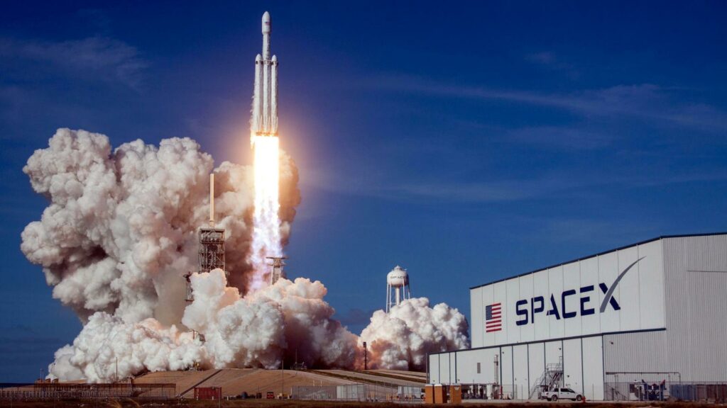
SpaceX’s historic CrewDragon has successfully launched into space on Saturday the 30th of May. The whole world had to hold their breath while watching the iconic moment of humanity coming into the new are of space flights.
The Crew Dragon launched astronauts from the United States for the first time since the last Shuttle flight in 2011. However, the shuttle itself completely differs from what we have ever had in the past.
Spaceflight had always been the fundamental goal for his pioneering company SpaceX. Elon Musk
The whole world is buzzing about the successful launch of the astronauts from their homeland. All the people involved in it, and especially software engineers became heroes for the United States. And as a team of software engineers ourselves , we are especially proud of one of them, who is Ukrainian — Oleksii Pakhunov, who played an important role in the software development of SpaceX projects .
After the Crew Dragon Demo-2 successful launch, a group of SpaceX software engineers posted on Reddit to answer the most thrilling questions of the platform’s users.
To be exact, the questions were answered by:
- Jeff Dexter – Flight Software and Cybersecurity engineer at SpaceX
- Josh Sulkin – the software design lead for Crew Dragon
- Wendy Shimata – Crew Dragon’s software team manager, who also worked on fault tolerance and safety of Dragon
- John Dietrick – Software Development Lead on Demo-2
- Sofian Hnaide – Crew Displays software engineer on Demo-2
- Matt Monson – Crew Dragon’s software engineer, who’s now a lead Starlink software engineer
The users of Reddit asked the team dozens of questions, revealing some previously unknown information. The Q&A session with the software engineer revealed many interesting details about Starlink, Crew Dragon, and other SpaceX projects.
Turns out that all software for the Falcon 9 , Falcon Heavy and Dragon spaceships is running on C++. Space X engineers are using object-oriented programming methodology (OOP). which is a programming paradigm based on the concept of “objects”, which can contain data, in the form of fields (often known as attributes or properties), and code, in the form of procedures (often known as methods).
Still, the most interesting part that caught our eyes is the UI part of the spaceships . If you are not aware of the Crew Dragon spaceship’s user interface, the pilots are using three large touchscreen panels, instead of a famous maze of manual controls. The Reddit users have also asked the development team about the touchscreens code base and development process.
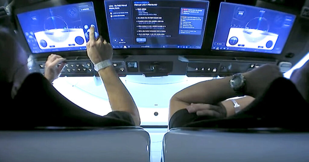
Surprisingly, the famous touchscreen interface is running on Chromium and is being fully written on JavaScript. JavaScript is a scripting language, internally designed to be used to create and control dynamic website content, i.e. The answer of SpaceX engineers has surprised many of the users, as no one expected to see a web development technology running on a spaceship in an open space.
We liked all the modern features that come with browsers out of the box Hnaide said during the AMA, adding that Chromium gave SpaceX access to lots of programmers already skilled with the technology.
The development team has used a self-written JavaScript library for the creation of UI components on the touchscreen. The engineers have designated that their team uses open-source libraries only as a last resort in case of any urgent needs, because of the quality control considerations.
Who would have thought, that SpaceX rockets fly with the software, that you can find on your Android phone? The SpaceX engineers have shown to the rest of the world that a web application, which was written in JavaScript and HTML, just like millions of websites here, on our Earth, can successfully run in an open space, showing the astronauts what they need to see while piloting a spacecraft.
That is clear evidence that you can use JavaScript to run important software on which people’s lives highly depend. This brings us to a certainty that there is no chance that Javascript will lose its position as the most used programming language in the world.
Looking for some more exciting content? Check out our other articles with some insights from a software development industry world: Grammarly – the most successful Ukrainian startup in 2019
Or maybe you are looking for a passionate team of JavaScript engineers yourself? Our team is ready to take responsibility for both the quality, budget, and timeliness of the product delivery.
Subscribe to us
- CASE 04.07.24 All You Need To Know About Modernizing Legacy Software
- CASE 25.06.24 AgroTech Trends in 2024
- CASE 20.06.24 Top 10 Healthcare Trends & Innovations in 2024
- CASE 11.06.24 Ultimate Guide On How To Evaluate A Software Development Partner
- NEW 05.06.24 Best Practices for Uploading Images Using AWS
- COMMUNICATION
- DEVELOPMENT
- OUTSOURCING
- REACT NATIVE
- REAL ESTATE
- Uncategorized
- Privacy Policy

Launch Library 2
Rocket launches, space events and crewed spaceflight.
The Launch Library 2 API is the official successor of the popular Launch Library API. It keeps its core features whilst also including everything the broader Space Launch Now API had to offer. The result is a large database delivering a more complete experience for each rocket launch and space event. The philosophy behind the API also remains unchanged : the entire database is accessible to everyone, for free.
Please note : all the API data is available at no cost for up to 15 requests per hour. For higher access rates, please check our Patreon
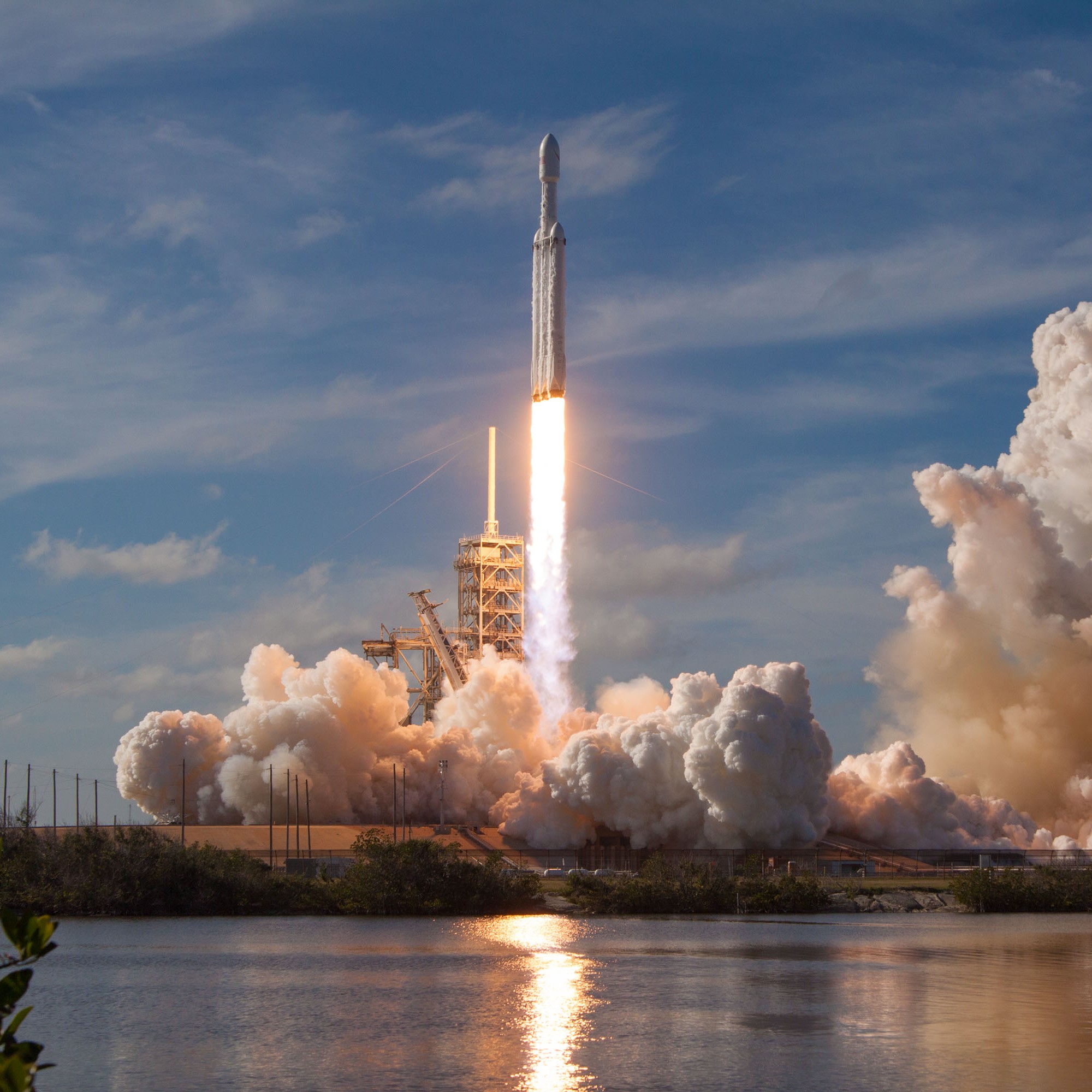
We track all orbital launches and a number of popular suborbital launches. Generally we will track all suborbital launches which aim to reach “space” or the Karman line and are live streamed, although, we will also occasionally track others by popular demand. The endpoint has a variety of filters and parameters, such as launch service provider, launcher config or spacecraft.
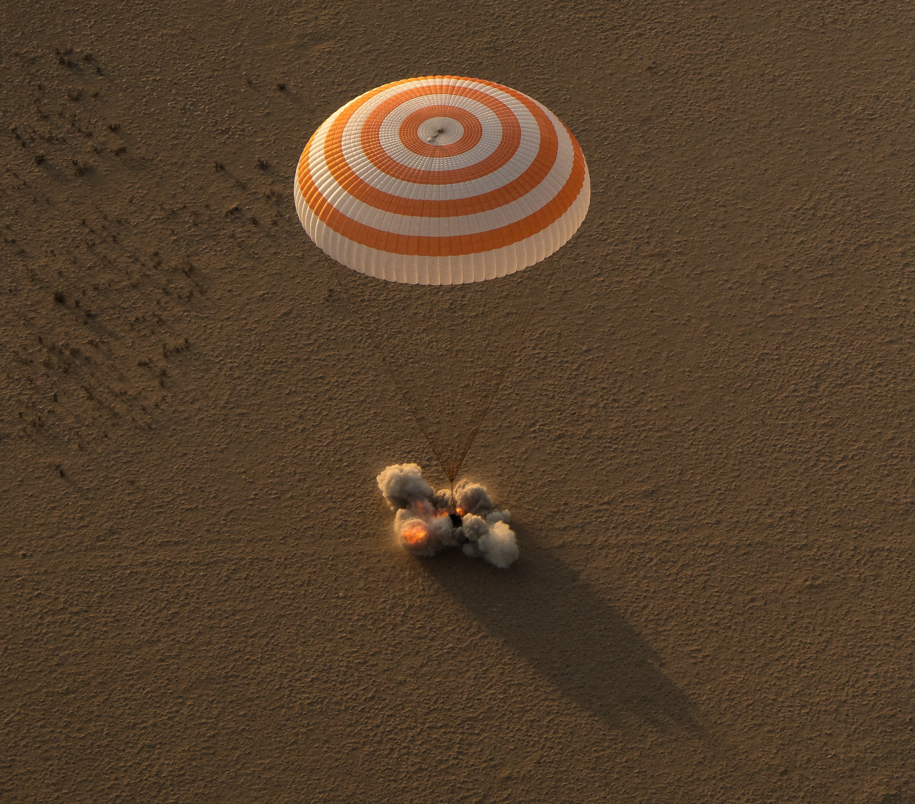
These are typically space events which aren’t covered by the standard launches. These events could be spacecraft landings, engine tests or spacewalks. The endpoint has a search filter.
These are agencies involved in spaceflight that are somehow connected to data in other parts of the API. These could be launch service providers, space agencies or rocket manufacturers. The endpoint has a variety of filters and parameters, such as type or country code.
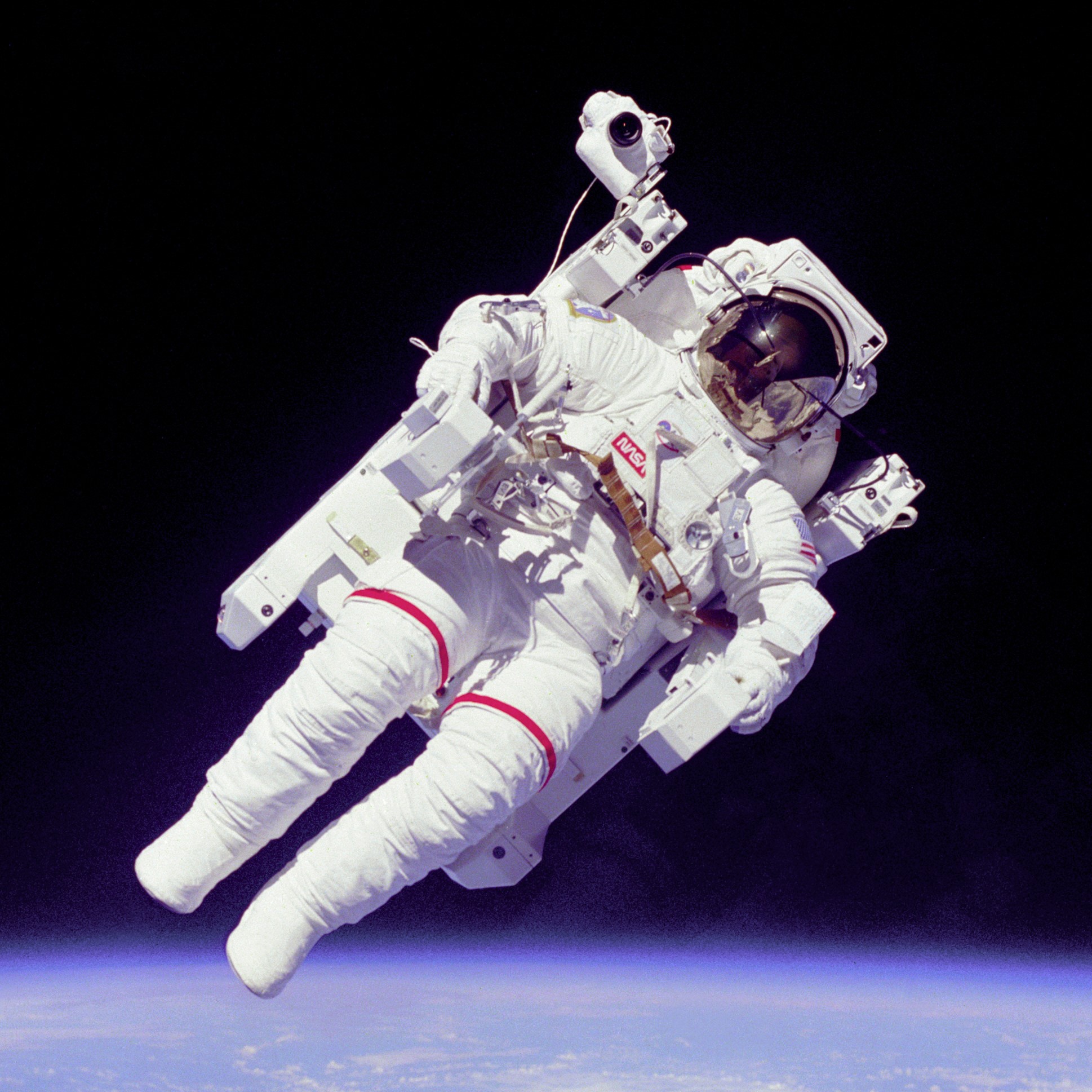
We aim to track every known astronaut past, present and future. The endpoint has a variety of filters and parameters, such as name, status or nationality.
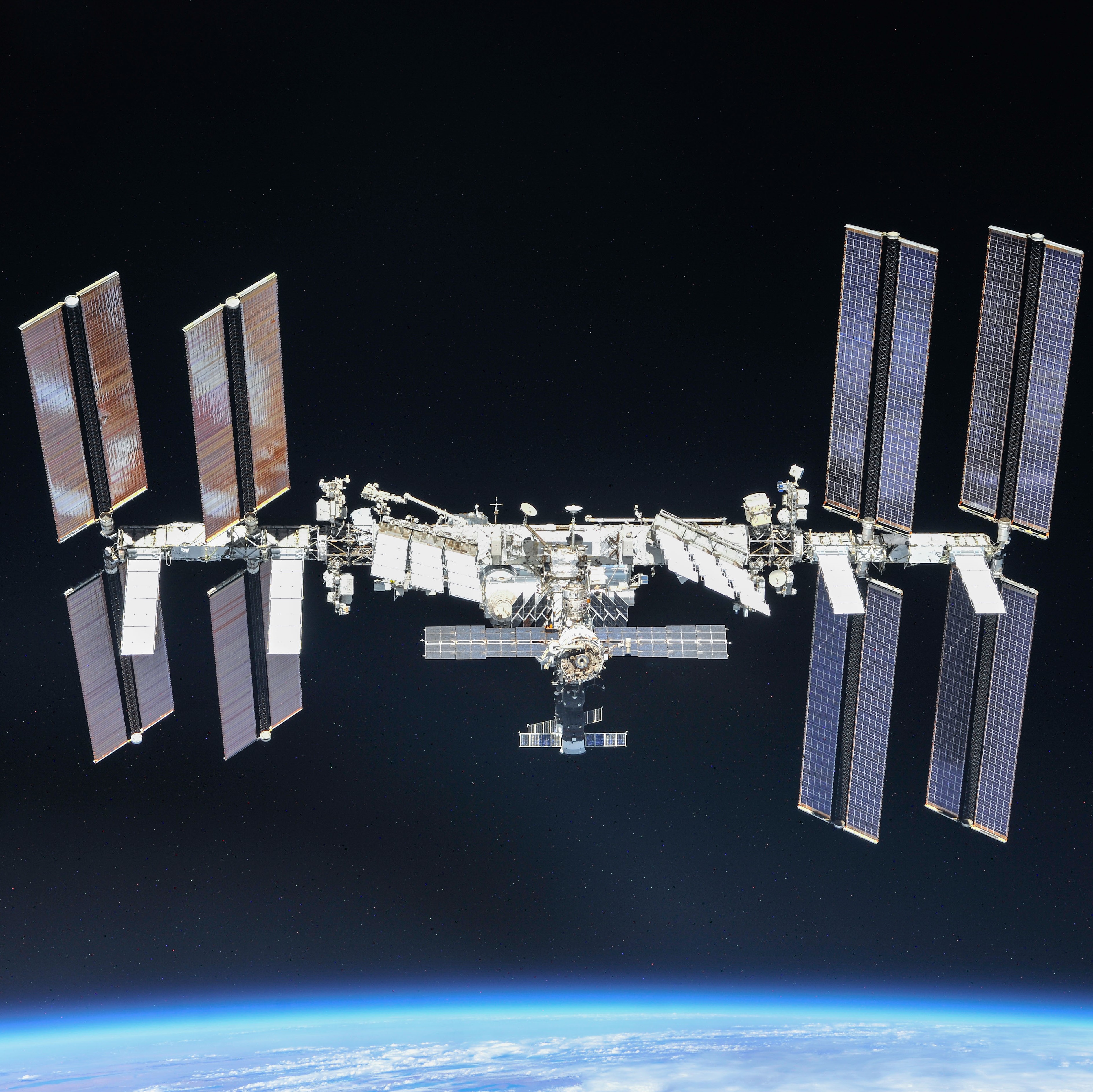
Space Stations
We aim to track every known space station past, present and future. The endpoint has a variety of filters and parameters, such as name, status or owners.
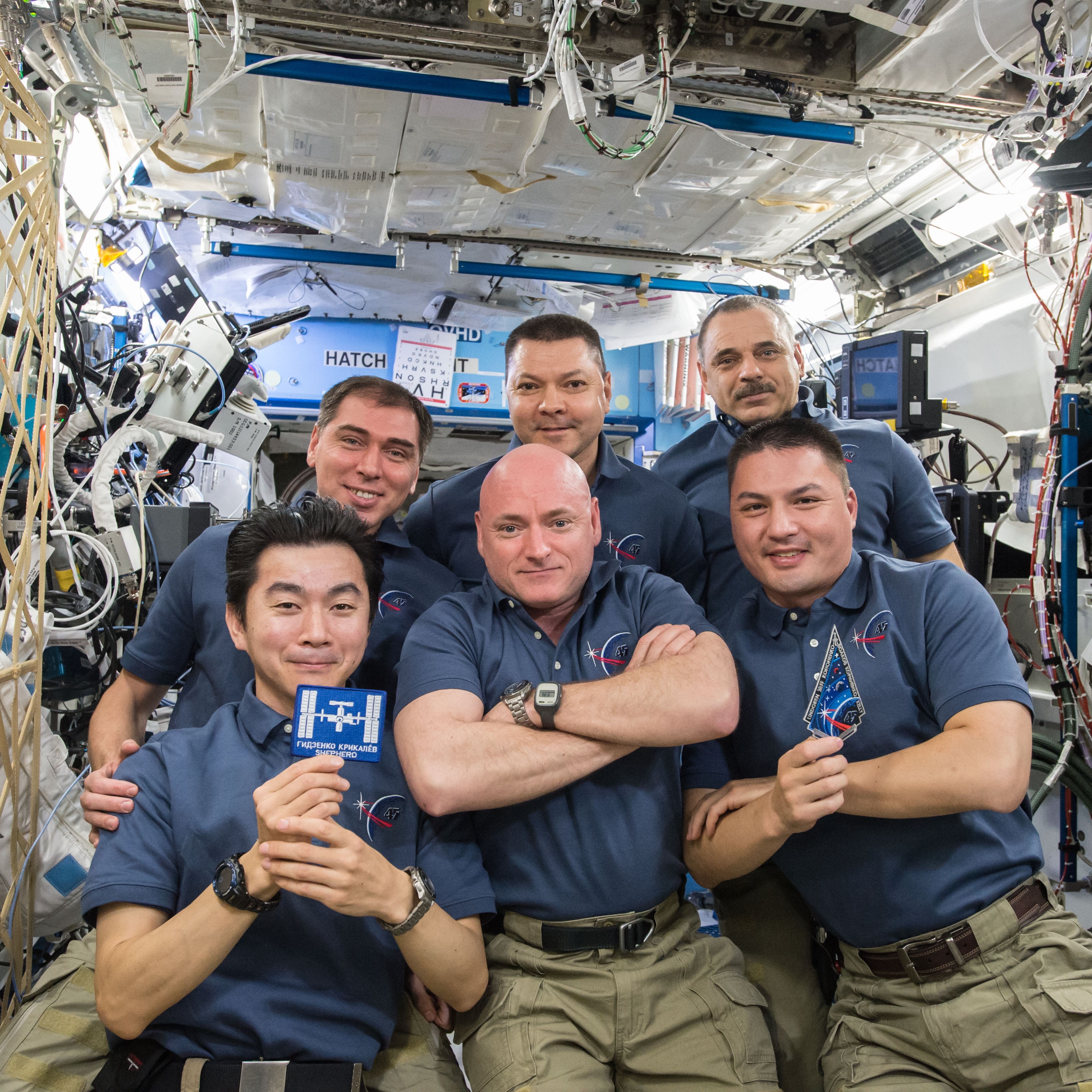
Expeditions
These are expeditions that have been made to space stations. The endpoint has a variety of filters and parameters, such as name or space station.
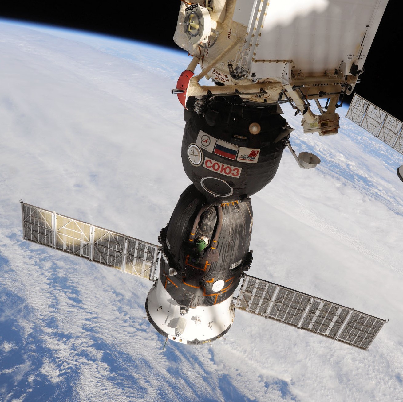
These are docking events that have occurred between a spacecraft and a space station. This is intended to track visiting vehicles, both crewed and uncrewed. The endpoint has a variety of filters and parameters, such as space station or docking location.
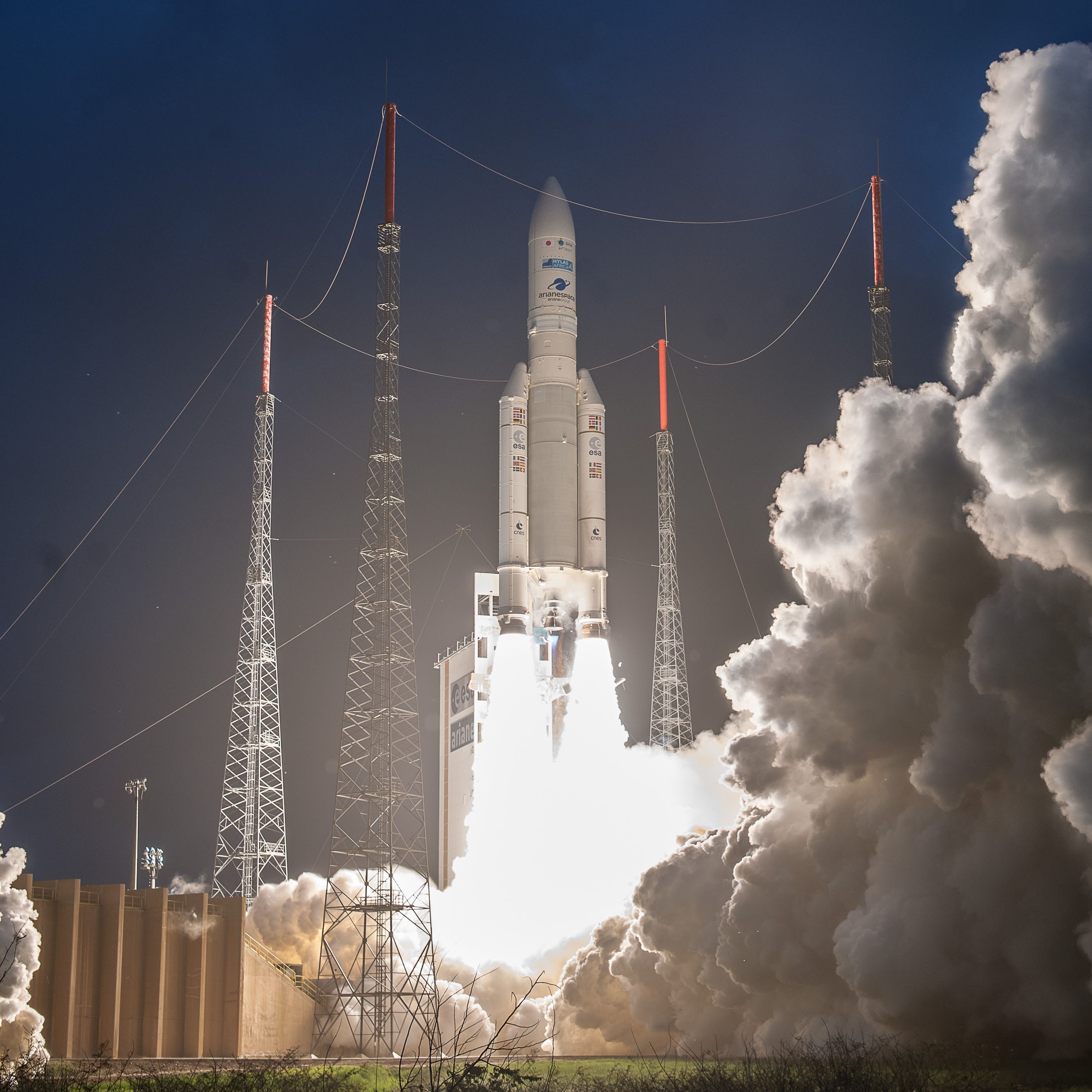
Launch Vehicles
This contains rocket configurations, such as ‘Falcon 9 Block 5’. We only have launch vehicles which are used by our launch objects, we don’t have launch vehicles which are used in launches we don’t track. The endpoint has a variety of filters and parameters, such as name, family or agency.
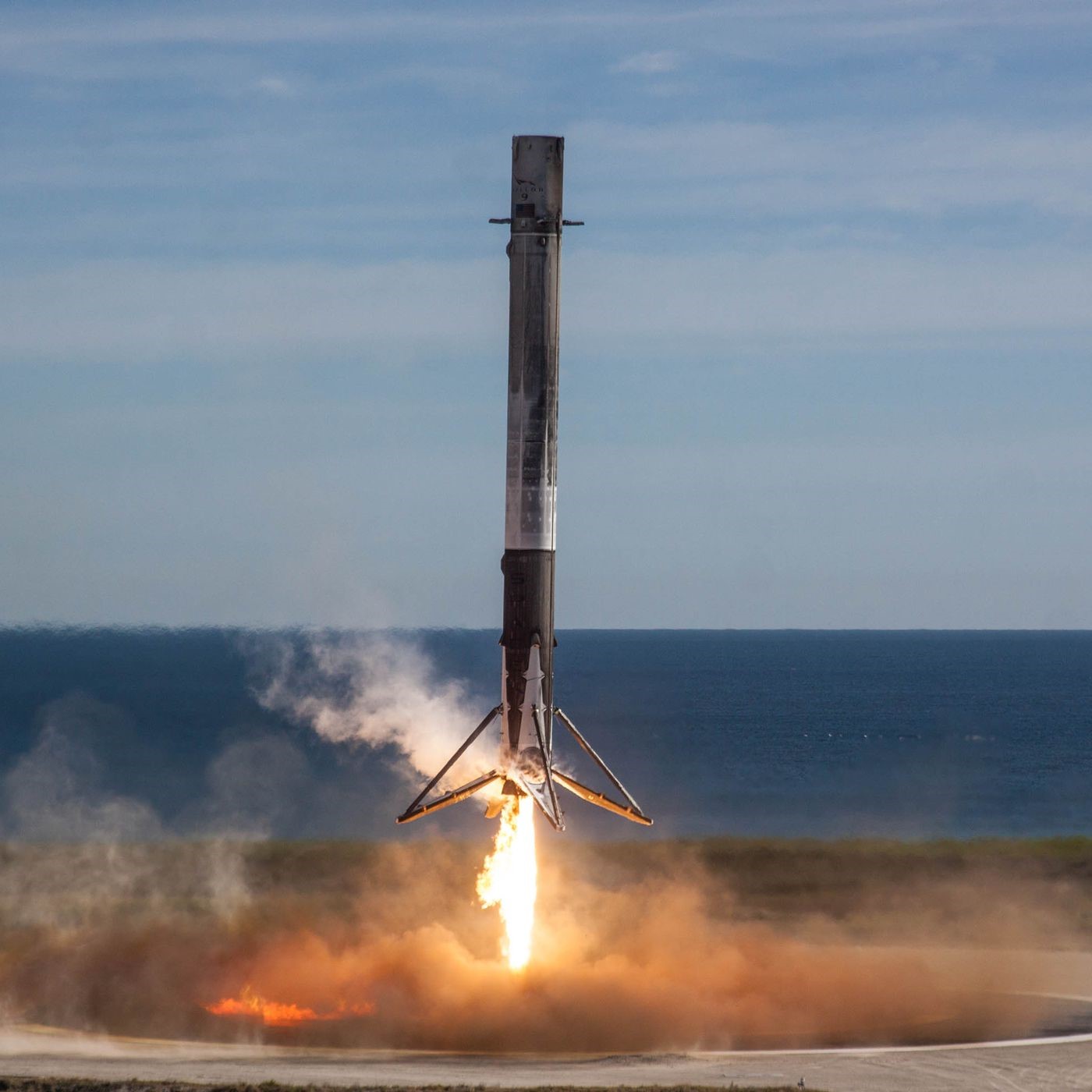
Reusable First Stages
We track first rocket stages when a launch vehicle can be used more than once such as the Falcon 9 cores used by SpaceX. The endpoint has a variety of filters and parameters, such as serial number or flight number.
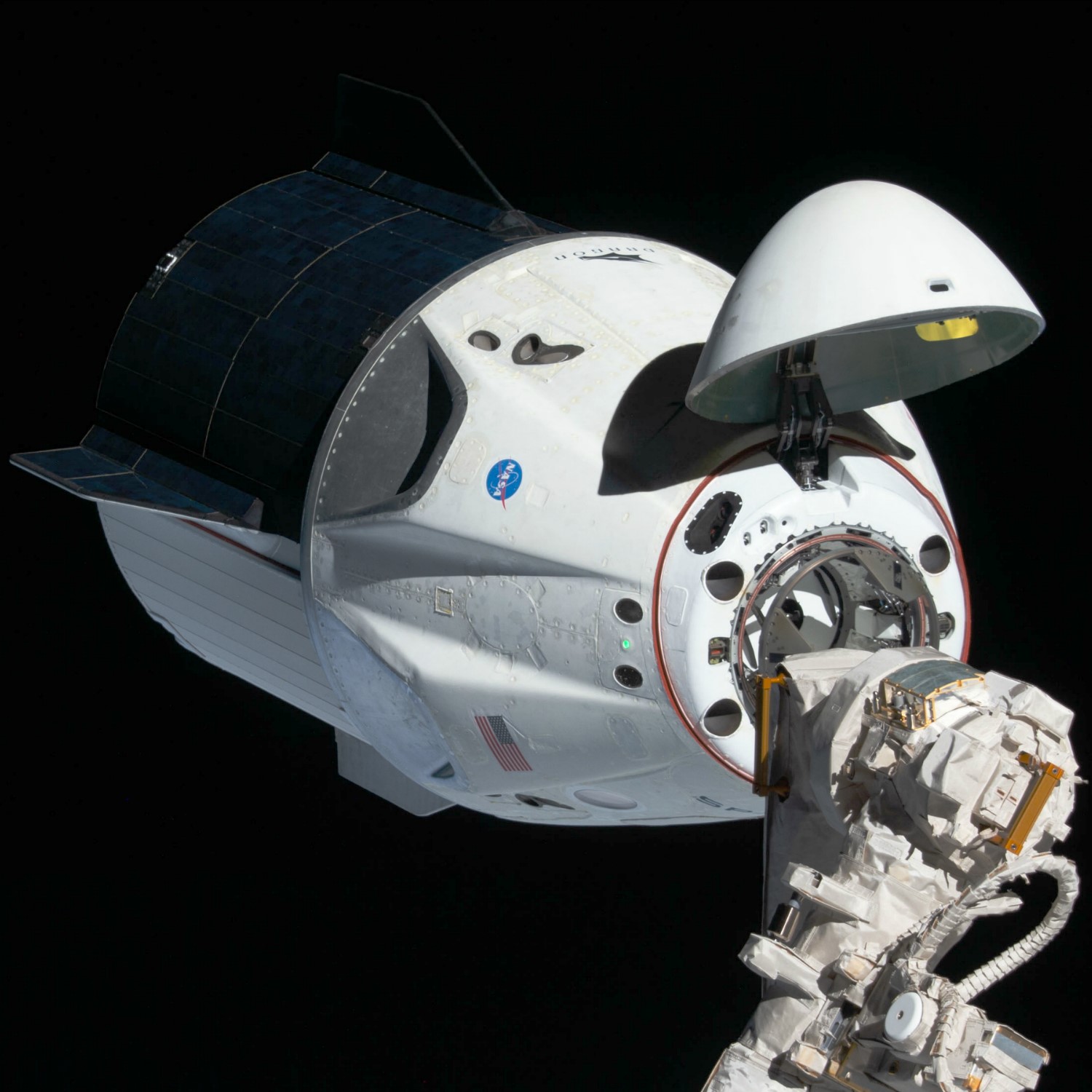
This contains a list of spacecraft configurations past, present and future, such as the “Mercury” or “Dragon” capsules. The endpoint has a variety of filters and parameters, such as name or status.
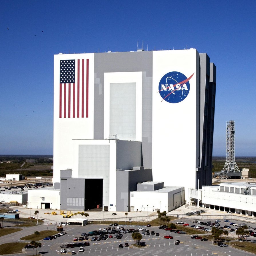
This contains a list of all locations where launch vehicles have flown from. These include locations such as Cape Canaveral, Florida and Kourou, French Guiana. The endpoint has a variety of filters and parameters, such as country code and name.
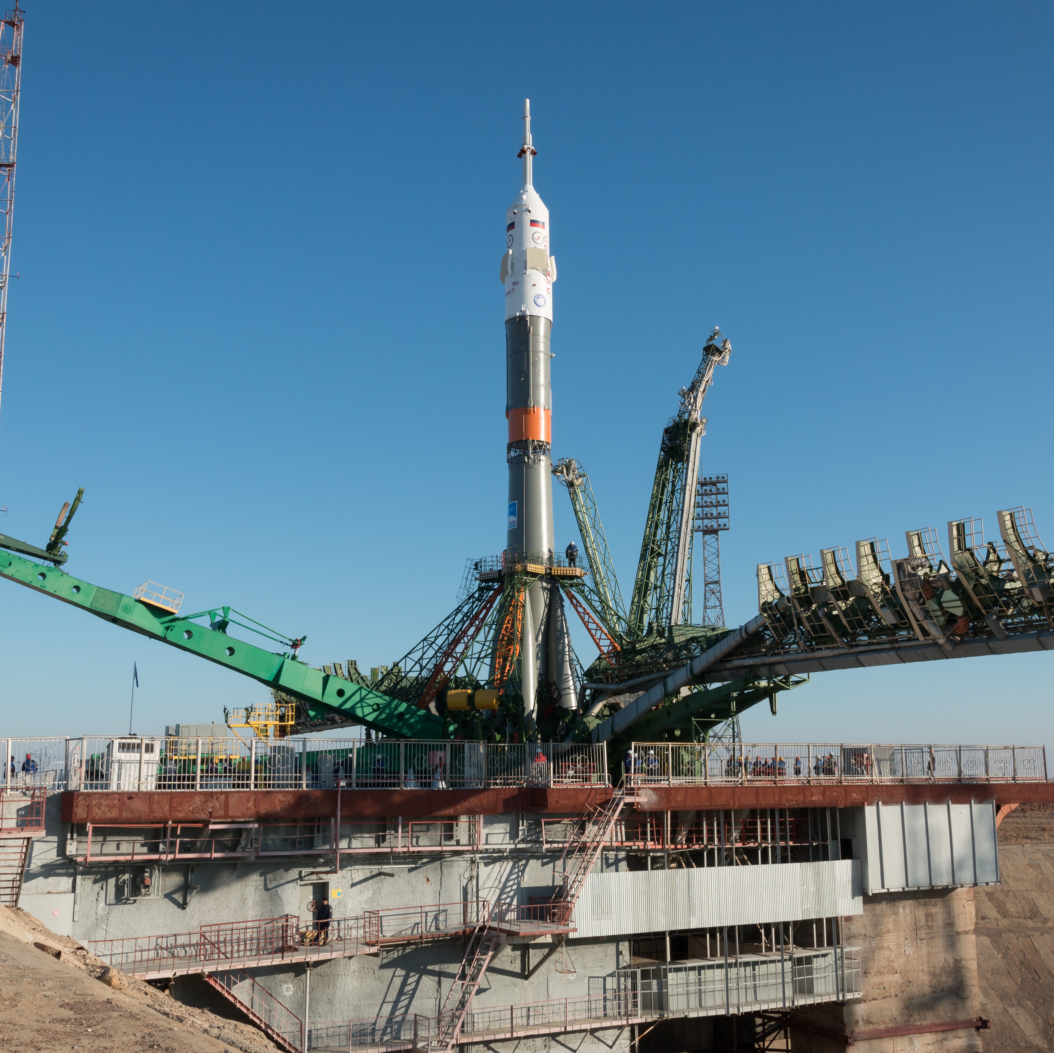
This contains a list of all pads where launch vehicles have flown from. This endpoint is similar to that of the location endpoint, however, is more specific and contains information on the individual pads at each location. An example of this pad would be 'Space Launch Complex 40', which is located in Cape Canaveral. The endpoint has a variety of filters and parameters, such as location id and name.
Navigation Menu
Search code, repositories, users, issues, pull requests..., provide feedback.
We read every piece of feedback, and take your input very seriously.
Saved searches
Use saved searches to filter your results more quickly.
To see all available qualifiers, see our documentation .
- Notifications You must be signed in to change notification settings
Expert system for space rockets launch decision-making on the basis of weather conditions
MinakovNV/Expert-system-for-space-rockets-launch-decision-making-on-the-basis-of-weather-conditions
Folders and files.
| Name | Name | |||
|---|---|---|---|---|
| 3 Commits | ||||
Repository files navigation
Expert-system-for-space-rockets-launch-decision-making-on-the-basis-of-weather-conditions.
Expert system for space rockets launch decision-making on the basis of weather conditions.
Relevance of work: The relevance of the expert system is to study the factors affecting the flight of space rockets and to create a system of space rockets launch decision-making on the basis of weather conditions, atmospheric pressure, humidity and wind force on the day of launch, that is why the development of this system is due to the practical value.
Objective of the work is to develop an expert system based on ADO technology and Object Oriented Delphi programming environment in order to reduce the likelihood of space rockets falling, depending on humidity, atmospheric pressure, wind speed and weather conditions.
Formulated goal required the resolution of the following tasks:
- Carrying out the debrief and analysis of the existing expert systems used in various fields of knowledge.
- Carrying out a correlation analysis between launches and fallings of rockets and weather conditions on this day.
- Modeling expert system, decision-making algorithms, rules.
- Development and testing of an expert system.
- Carrying out experiments.
Research methods: • Theoretical (analysis, comparison, synthesis). • Practical (experimental research, the development of decision theory, modeling, UML modeling).
Target of research – the effect of weather conditions on the fall of space rockets to Earth, and the subject of research is the development of the expert system of space rockets launch decision-making, based on weather conditions.
The hypothesis is that the system is designed to determine the minimum risk probability up to 80% for launching space rockets.
The novelty of the work lies in multicriterion modeling system of space rockets launch decision-making with minimal risk, different in terms of correlation analysis between launches of rockets and weather conditions at this time.
Practical significance: This development can be used by spaceports to make decisions on the launch of rockets, depending on weather conditions.
Implementation of the results: Based on the results of scientific work, there was developed the expert system of rocket launch decision-making, depending on weather conditions.
Almaty 2016; Minakov Nikita;
- Pascal 100.0%
by Nicholas Carlini 2020-12-19
This year I entered in JS13K 2020, a game jam for JavaScript games in under 13KB (total size). I wrote a 3rd-person space shooter game, building on top of game engine I built last year for a doom clone .
Clicking the video above (or HERE ) will take you to the game. Source code is available here .
I don't really care (much) about making games, or even about making them particular fun (maybe that's why I never actually do well during the judging...) but I do like small time-constrained projects with tools I normaly don't use.
And making games pointless in JavaScript is just about as far as you can get from academic computer science research. Last year's entry was focused on building the game engine itself, and just making everything run at all. So, this year I decided it would be a good opportunity to build something “more”. So this means that I tried to just pack in as much game-like-stuff as possbile. The remainder of this post describes most of these.

Starting from (non)-Zero
They say the number one mistake of trying to make a game is building a game engine. Well, I'd already done that last year. So this year the first thing that I did was take last year's code and gutted everything out of it except for what was absolutely necessary for basic rendering. Anything that I wasn't absolutely sure I needed got removed, because I knew that I could always go and pull code back in if I wanted it back.
This gave me a relatively clean slate game engine to start with. I wasn't sure where this game was going at first, but I knew that I wanted to blow things up in space. My initial vision was as a cross between Descent and Asteroids , and it ended up somewhere kind of like that.
This gave me an initial plan. First, I need to be able to fly around. Then, I need to be able to shoot at the asteroids. And then I'd see where things stood from there. I started off by putting the camera in a skybox , that has stars rendered out at infinity. Then the game making started.
Player and Camera Movement
I spent at least a few days playing around with variations of player movement. Initially it was truly Asteroids-like where player momentum was always preserved, but in three dimensions that was really rather disconcerning, and just not very fun having to manage accelerating the “proper” direction in order to move in a different direction. So I eventually settled on just fairly standard movement, where the player automatically slows down and stops even though there's no physical reason this would happen in space.
The camera moves by following around the player. Instead of directly following exactly behind the player at all times, it lags behind ever so slightly. This is achived by making the camera have a specific target in mind (always in the correct position right behind the player), but on every frame only moving (say) 20% of the way there. This gives a kind of exponential moving average of the player's past positions, and gives a nice appearance of movement instead of the much more rigid option of following the player directly.
The problem with this simple movement is that even though the player is moving around a lot, and moving quickly, it doesn't feel that way. Especially when there are no other objects in the scene, it's literally impossible to know the difference between moving quickly and standing still: the skys in the backdrop never move, and so there's no frame of reference. The camera lagging behind the player adds some feel of movement, but it just doesn't look right.
So what's the solution here? I briefly tried experimenting with putting a bunch of asteroids in the space so no matter where you looked there was something to see you moving by. But this cluttered everything up and was just generally very confusing. There was already too much happening even without a game going on.
So the solution I decided upon was to add little bits of just glittery-things that represent a sort of aether . It's always present, and the player moves though it. Now in order to make the game actually playable, it's not possible to actually fill the aether and render every particle in an infinite space. So what I do is generate a single 10x10x10 aether cube. Then, I tile the entire space with this single cube repeating over and over. (So if a player managed to move exactly 10 meters in one direction, they would see exactly the same configuration of particles. I figured this is unlikely to happen when there are three degrees of freedom.)
Now of course I can't actually tile the entire space with this cube, and this doesn't directly solve the problem. But I can pretend I have. Given wherever the player is, I redner only the cube for the 8x8x8 box centered (approximately) around the player. Doing this is actually fairly trivial with the following code:
var base = NewVectorFromList(camera_position._xyz().map(x=>(x>>5)<<5));
range(8*8*8).map(z => {
var v = NewVector((z&7)-3,((z>>=3)&7)-3,(z>>3)-3);
if (v.vector_length() < 3) {
glitter.position = base.add(v.scalar_multiply(32));
glitter.render();
}
The one detail here that important is that the aether cube should be centered not around the actual ship (which would be the physically realistic thing to do) but around the camera. The reason here is subtle: it gives a much more dramatic feeling of movement. In fact, by adjusting the density of the particles in the space it is possible to make movement feel much faster or slower by adjusting the rate at which the camera passes them by. Compare the two images above. Both travel at exactly the same speed (notice the objects in the background move at the same rate) but the the image on the left feels much faster.
Particle System
The next thing I was worried about was how to make sure the player couldn't easily get lost in space. For this, I wanted to have a nice big star that was always visible and could easily be located to fly around. And this means particle systems.
A particle system is one of the core building blocks of most games: every time there are sparks, or smoke, or fire (or anything procedural of this nature) there's a particle system that's backing it. At the core, a particle system is just a way of creating an effect by rendering a bunch of independent particles that each follow an identical set of (randomized) rules.
Particle systems are rendered with the same two components as any objects in a game engine. The first is the shaders that actually draw the particles. My particles were going to be really simple and have just a few attributes. Particles are circles with a given position, velocity, color, size, and opacity. That's it. They can't accelerate, be affected by gravity, change shape, or anything else.
This lets me render particles with a really simple vertex shader that just places individual gl.POINTS in the correct position of the correct size
gl_Position = projection_matrix * object_position;
transparency *= smoothstep(1., 0., (u_time-a_settings.x)/(a_settings.y-a_settings.x));
gl_PointSize = (2000./gl_Position.w) * (2.+transparency) * size;
v_normal = a_normal;
And then in the fragment shader makes them the circles of the correct color
vec2 from_center = 2.*gl_PointCoord.xy-vec2(1,1);
out_color.rgb = v_color.rgb;
out_color.w = smoothstep(1.,0.,length(from_center)) * transparency;
The second component of a particle system is how to decide where the particles are actually supposed to be drawn. This started with the simplest---but least efficient---implementation possible. Every frame, I manually (in JavaScript) computed the new location of each particle and updated the particle system's buffer with the new position and color buffers with the updated values. This is clearly very slow, but it does work, and served as a reasonable baseline. I could render something like 5,000 particles before things got slow. (Modern computers are amazing. This is 300,000 particle computatinos per second in JavaScript copying over to the GPU.)
This wasn't quite enough. As an improvement on top of this, I read a little bit into webgl's Transform Feedback mechanism, which is the “correct” way to be doing this: it basically lets the GPU compute the new location of each next particle on each frame. This can get really fast---millions of particles per second---but is a bit overkill. The shortest implementation I could get for this was far too much space to fit in a 13k game.
Eventually I had an important realization. Everything I was doing in JavaScript to manually set the particle's new position, and new opacity, was a completely linear function of the initial position, initial velocity, and opacity. So all I have to do is store these initial values, and then instead of updating the position every frame, I just need a single scalar recording the age of every particle. I can pass this age to the shader, and then have the shader itself automatically compute where it should be, and what the opacity and size should be, given just the age.
Except I can do one better. Instead of having to update the age of every particle on every frame (this would still be a lot of work copying to the GPU every frame) I record, once, at what time each particle was created. Then, each frame, I only need to pass in a single float: the current time. Each particle can then compute how long it's been alive, and therefore what its attributes should be. The JavaScript side of this code looks like this:
update(dt, other_max) {
for ( var i = 0; i < this .ages.length; i++) {
if (( this .ages[i] -= dt) < 0) {
var [ pos , vel ] = this .particle_start(dt, max);
this .ages[i] = this .maxage*1000*( this .use_random||Math.random());
this .setup_particle(current_time(), i, pos, vel)
}
this .rebuffer()
The JavaScript particle system code keeps track of just one float per particle that is updated on every frame: how much longer it is allowed to live for. This age is decremented every frame, and if it's ever less than zero, then I create a new particle in it's place. The shader can now do all of the work, and compute where it's supposed to be, the opacity, and color---all given just the current time.
And now it's time for something completely uselss but really fun. Let's add some lens flare. Why? Because I want to.
I implemented the lens flare by mashing together a bunch of different ideas I found online. Briefly, all that's done is drawing a bunch of nearly-transparent circles at different poitns on the screen (if the player faces towards the star that generates the lens flare). In order ot make things somewhat nicer, there's a slight chromatic aberration that shifts the positions of the colors slightly based on the angle from the light.
It's time to start making this a space shooter . We've done the space part, let's add the shooting.
The idea is that while the player's ship rotates fairly slowly, the shooting will always target exactly where the cursor is pointing at any point in time. This makes it much less disorienting to shoot, and makes everything generally easier. Implementing it takes a bit of work, though.
Given the current (2d) mouse coordinates in screen-space, I now have to figure out what this corresponds to in world-space. Now this is easy without space constraints: take the world projection matrix (that converts from world space to screen space), compute it's inverse, and---bam!---you have the screen space to world space matrix. It's now just a single multiplication to solve our problem.
The problem with this is that computing the inverse of a matrix takes a lot of code. Several hundred bytes of code, a reasonable fraction of the total space constraints on just a single function is a hard pill to swallow.
Except here's the thing. There's a builtin inverse function in webgl. So instead of creating the correct view projection matrix in JavaScript land, I'm only ever going to create the correct inverse view matrix. Then, when I need to know how to take a 2d world position and project it into 3d position, I can multiply by this inverse view matrix.
And now, the first line of the vertex shader just computes the inverse and goes on with life. Is this ugly? You bet. But it's really short!
var mouse_position_3d = mat_vector_product(proj_mat, NewVector(mouse_dx*2e5, mouse_dy*2e5, 1e5, 1e5)).add(camera_position);
Shooting now is just a matter of making the right particle effect. This is mostly a matter of just playing around with the parameters that I have available (how long the particles live for, their size, how quickly they fade, and the color). Eventually I decided on the above animation that I thought looks quite nice.
Okay. Now we have a game where you can fly around a star, and shoot at ... nothing. Let's fix that.
There's not really much to this piece. I added a few enemies that fly around and shoot at you. I made each of the enemies in blender . The fact that the ships have to be low poly helps here, because I am truly awful at anything design.
I'll talk about making the enemies do something interesting later on in the section on the Enemy AI. For now, they just sit and look (not so) pretty as a target.
Collision System
So now there are enemies ... but we can't actually shoot them because there's no way to detect if we hit them or miss. The easy and cheap thing to do is to just compute the distance between the point of the enemy and the ray of where you shot, and if it's close enough, declare it a hit. The problem with this is that while people may not notice small errors when shooting at enemies, they certainly aren't going to be forgiving about being shot .
If your spaceship isn't a perfect sphere, and an enemie misses you but you take damage, people will bitterly complain. So I'm going to have to detect precise collisions eventually. It turns out that this is, again, a time where we can just say computers are fast, just brute force it. Every lazer, every frame, will check its collision with every possible object that can be shot at. To do this, I literally check every single ray-triangle intersection in the object. Tens of thousands of checks every frame! But it works!
function does_hit ( position , direction , filter ) {
objects.map(other => {
other.sprites.map((sprite, sid) => {
sprite.b_positions.map((tri,idx) => {
tri = tri.map(x=>mat_vector_product(sprite.rotation, x).add(sprite.position))
var distance = ray_triangle_intersect(position, direction, ...tri);
if (distance > 0) {
return true ;
}
})
})
})
return false ;
The actual code is a little more efficient, and has a few early-stop checks that skip collision checks for objects that are too far away to ever possibly collide. It also doens't just report if there's a hit or miss, but returns which object and at what position the hit occurred. But this is just multiplying the distance by the direction, so I've left it out too.
So once contact occurs, it's time to make a show of it. The first few times something gets hit, it just does a particle hit-effect and shows that something happened. Doing this naively is fairly simple, but doesn't loook great.
It's now time to make the enemies blow up. To do this I basically stole the code I used last time in my doom clone: every object breaks apart into the components that constructed it, and flies out towards infinity. This gives a fairly satisfying result.
HUD Tracking
It's really easy to get disoriented in three dimensions. To help give the player some sense of direction, every enemy will have a HUD tracker that shows its current position if it's on the screen, and if it's off the screen will give an arrow pointing to where that enemy is.
Making the projection work in this way actually is fairly trivial. I render it as if it's any other object in the scene, take the target's position in three-dimensional space, and project that on to the two dimensional screen with the same view projection matrix that does any of the work. However, in order to ensure the HUD always shows up, disable the depth buffer test and always draw the tracker on the top of the screen. Doing this literally just requires a few lines of code changed to the camera
Showing an arrow to where the object is if it's off-screen takes a tiny amount more work, but not much.
if (v_off_screen > 0.) {
float a = -atan(uv.y, uv.x);
vec2 x_dir = vec2(cos(a),sin(a));
vec2 y_dir = vec2(-sin(a),cos(a));
out_color.w = dot(from_center,x_dir) > -1. && dot(from_center,x_dir)+abs(dot(from_center,y_dir))*3. < -.3 ? 1. : 0.;
out_color.w = min(abs(from_center.x),abs(from_center.y)) < .25 ? 1. : 0.;
Building Objects
In order to put objects into the game there needs to be some way to specify how they look. Last year I used the object lathe which lets you build up objects from simple primitives. However, it was really rather difficult to build up better looking objects.
So this year I decided to build a .obj file format compressor. Naively, an object is a list of triangles, each polygon requiring an XYZ triple. Now if you export a standard cube as a .obj file, just about the smallest file you can get is 136 bytes. Given that a single spaceship is going to be tens of objects, and I'll want five of them, that would almost completely eat up my entire space budget in ojbects alone.
Now this wouldn't at all work. So I decided to do something to shrink the objects fairly considerably. I managed to get something like a 100x compression ratio when compared to the basic .obj files. How did I do that? Well, this is already really long, so I think I've decided that I'll write up a completely separate thing on how to do 3d object compression. I think I'll be able to do better, and so want to spend some time getting it right.
Making a game
Alright now I have everything needed to make a game. The final piece left is to actually ... make it a game. This is where I spent the least time, and does it ever show!
I eventually decided a survival game where the goal is just to live as long as possible. Enemies keep coming, and with increasing frequency, until eventually you get overwhelmed and die. This means that the actual game component is fairly minimal, and doesn't require much work on top of what's already built.
Enemies in this game are just about as dumb as they come. In fact, the AI is basically designed to make entertaining targets to shoot, and does basically nothing intelligent to attack the player.
At any point in time, enemies have a target in mind. They will move towards the target, and if it's something that can be shot at (and they're facing towards it) will shoot at it. Enemies can only turn at a fixed rotation per second, and this gives the nice image as if they were really flying around with some momentum.
By default, enemies will target the base and attack it, and will completely ignore the player. This changes when they get shot at: if the player shoot (near) an enemy, then they'll switch target to the player.
If the enemy gets within a small distance of the player, the enemy will enter a new RUN AWAY state. It sets a target at a random offset away from the player, and moves that way until it gets far enough that it can go back to attacking. If the player turns to chase the enemy, then the enemy will keep going in a similar direction more or less forever until it gets destroyed.
The one piece of intelligence I added was some aim-prediction. Instead of shooting directly at wherever you are right now , the enemies will shoot so that they will hit wherever you will be once the bullet arrives. There's probably some kind of smart way to actually compute this, but I got really lazy and just iteratively refine where I expect the player to be ten times and call it good enough.
var predicted_location = me.position;
var vel = lazerspeed( this .damage);
range(10).map(x=> {
var time_to_hit = predicted_location.distance_to(start_pos)/vel;
predicted_location = me.position.add(me.velocity.scalar_multiply(time_to_hit))
Game over animation
Given that the goal of the game is to stay alive as long as possible, I wanted to have some nice effects for when you lose and die. So when the ship gets sufficiently damaged, the screen slowly pans back as time slows down and shows you get blown up.
There's probably more to making this game than I remember now. But given that it's already three months since I made this and I'm still procrastinating the writing, this is all you'll get.
I guess the obvious question is what comes next. I don't have any desire to do this again, because now that I've mostly explored the space of what needs to go into a game it's less interesting than it was when I didn't know how to do it. Maybe next year I'll think of something new that would be surprising to be able to fit in 13k.
JS Tutorial
Js versions, js functions, js html dom, js browser bom, js web apis, js vs jquery, js graphics, js examples, js references, javascript assignment, javascript assignment operators.
Assignment operators assign values to JavaScript variables.
| Operator | Example | Same As |
|---|---|---|
| = | x = y | x = y |
| += | x += y | x = x + y |
| -= | x -= y | x = x - y |
| *= | x *= y | x = x * y |
| /= | x /= y | x = x / y |
| %= | x %= y | x = x % y |
| **= | x **= y | x = x ** y |
Shift Assignment Operators
| Operator | Example | Same As |
|---|---|---|
| <<= | x <<= y | x = x << y |
| >>= | x >>= y | x = x >> y |
| >>>= | x >>>= y | x = x >>> y |
Bitwise Assignment Operators
| Operator | Example | Same As |
|---|---|---|
| &= | x &= y | x = x & y |
| ^= | x ^= y | x = x ^ y |
| |= | x |= y | x = x | y |
Logical Assignment Operators
| Operator | Example | Same As |
|---|---|---|
| &&= | x &&= y | x = x && (x = y) |
| ||= | x ||= y | x = x || (x = y) |
| ??= | x ??= y | x = x ?? (x = y) |
The = Operator
The Simple Assignment Operator assigns a value to a variable.
Simple Assignment Examples
The += operator.
The Addition Assignment Operator adds a value to a variable.
Addition Assignment Examples
The -= operator.
The Subtraction Assignment Operator subtracts a value from a variable.
Subtraction Assignment Example
The *= operator.
The Multiplication Assignment Operator multiplies a variable.
Multiplication Assignment Example
The **= operator.
The Exponentiation Assignment Operator raises a variable to the power of the operand.
Exponentiation Assignment Example
The /= operator.
The Division Assignment Operator divides a variable.
Division Assignment Example
The %= operator.
The Remainder Assignment Operator assigns a remainder to a variable.
Remainder Assignment Example
Advertisement
The <<= Operator
The Left Shift Assignment Operator left shifts a variable.
Left Shift Assignment Example
The >>= operator.
The Right Shift Assignment Operator right shifts a variable (signed).
Right Shift Assignment Example
The >>>= operator.
The Unsigned Right Shift Assignment Operator right shifts a variable (unsigned).
Unsigned Right Shift Assignment Example
The &= operator.
The Bitwise AND Assignment Operator does a bitwise AND operation on two operands and assigns the result to the the variable.
Bitwise AND Assignment Example
The |= operator.
The Bitwise OR Assignment Operator does a bitwise OR operation on two operands and assigns the result to the variable.
Bitwise OR Assignment Example
The ^= operator.
The Bitwise XOR Assignment Operator does a bitwise XOR operation on two operands and assigns the result to the variable.
Bitwise XOR Assignment Example
The &&= operator.
The Logical AND assignment operator is used between two values.
If the first value is true, the second value is assigned.
Logical AND Assignment Example
The &&= operator is an ES2020 feature .
The ||= Operator
The Logical OR assignment operator is used between two values.
If the first value is false, the second value is assigned.
Logical OR Assignment Example
The ||= operator is an ES2020 feature .
The ??= Operator
The Nullish coalescing assignment operator is used between two values.
If the first value is undefined or null, the second value is assigned.
Nullish Coalescing Assignment Example
The ??= operator is an ES2020 feature .
Test Yourself With Exercises
Use the correct assignment operator that will result in x being 15 (same as x = x + y ).
Start the Exercise

COLOR PICKER

Contact Sales
If you want to use W3Schools services as an educational institution, team or enterprise, send us an e-mail: [email protected]
Report Error
If you want to report an error, or if you want to make a suggestion, send us an e-mail: [email protected]
Top Tutorials
Top references, top examples, get certified.
Spacecraft Trajectory Optimization
- Introduction
- Prerequisites
- Table of Contents
1.1.1 Departure and Arrival Locations
1.1.2 departure and arrival times, 1.1.3 spacecraft mass and constraints, 1.1.4 thrust and propulsion system, 1.1.5 environmental factors, 1.1.6 mission constraints, 1.2.1 spacecraft state variables, 1.2.2 control parameters, 1.2.3 time parameters, 1.2.4 thrust profiles, 1.2.5 impulsive burns, 1.3.1 performance measures, 1.3.2 time-related objectives, 1.3.3 targeting and accuracy, 1.3.4 risk and safety considerations, 1.4.1 dynamics and kinematics, 1.4.2 propulsion and fuel constraints, 1.4.3 environmental and safety constraints, 1.4.4 mission-specific constraints, 1.4.5 resource and operational constraints, 2. mathematical models in spacecraft trajectory optimization, 2.1 equations of motion, 2.2.1 inertial coordinates, 2.2.2 classical orbital elements, 2.2.3 modified equinoctial orbital elements, 2.1.1 impulsive model, 2.1.2 continuous model, inertial coordinates, equations of motion in scalar and cylindrical form, 3.1.1 single-shooting, 3.1.2 multiple-shooting, 3.2.1 pontryagin’s minimum principle, 3.2.2 variational methods, 4.1 setting up the environment, 4.2 problem formulation, 4.3 optimization algorithm implementation, 4.4 visualizing and analyzing the results.
Spacecraft trajectory optimization plays a pivotal role in the realm of aerospace engineering, enabling the design of efficient and feasible paths for spacecraft to traverse between different points in space while considering a multitude of constraints and objectives. In this post we aimed to delve into advanced techniques and methodologies for spacecraft trajectory optimization.
Space missions demand precise and optimal trajectory planning to achieve desired objectives, such as minimizing fuel consumption, reducing mission duration, reaching specific targets, or avoiding hazardous areas. Additionally, spacecraft dynamics, propulsion systems, and mission constraints impose numerous challenges that necessitate the application of sophisticated optimization methods.
This post will offer a comprehensive exploration of spacecraft trajectory optimization, encompassing both theoretical foundations and practical implementation using Python. By investigating diverse optimization algorithms, formulating optimization problems, and employing visualization techniques, readers will develop the necessary expertise to address intricate trajectory optimization challenges.
To engage in this tutorial effectively, a solid understanding of astrodynamics is presumed, encompassing key concepts such as orbital mechanics, spacecraft dynamics, and orbital transfers. Proficiency in optimization theory and numerical methods is also advantageous. Furthermore, competence in Python programming is essential, as we will utilize prominent scientific libraries like NumPy, SciPy, and matplotlib to realize and evaluate spacecraft trajectory optimization algorithms.
The primary objectives of this tutorial are as follows:
- Attain an encompassing comprehension of spacecraft trajectory optimization, encompassing problem formulation, decision variables, objective functions, and constraints.
- Explore advanced optimization algorithms suitable for spacecraft trajectory optimization, including both direct and indirect methods.
- Implement spacecraft trajectory optimization algorithms utilizing Python, employing numerical techniques and optimization libraries.
- Visualize and analyze optimized trajectories to gain insightful perspectives on spacecraft trajectory performance.
By the conclusion of this tutorial, participants will possess the requisite knowledge and competencies to address intricate spacecraft trajectory optimization problems. They will be proficient in formulating trajectory optimization problems, implementing optimization algorithms in Python, and effectively interpreting and visualizing results. This acquired expertise will empower them to contribute to the design and planning of space missions, enabling the realization of efficient and precise spacecraft trajectories for a broad spectrum of applications, ranging from satellite deployments to interplanetary missions and beyond.
To make the most of this tutorial, you should have a solid understanding of astrodynamics, optimization theory, and Python programming. Familiarity with numerical methods and scientific computing libraries such as NumPy, SciPy, and matplotlib will be highly beneficial.
By the end of this tutorial, you will be able to:
- Understand the fundamentals of spacecraft trajectory optimization.
- Formulate trajectory optimization problems with different objectives and constraints.
- Implement advanced optimization algorithms to solve spacecraft trajectory problems.
- Visualize and analyze the optimized trajectories using Python.
1. Problem Formulation
Spacecraft trajectory optimization is a complex and challenging area of research in astrodynamics. It involves determining an optimal trajectory for a spacecraft while considering specified initial and terminal conditions and minimizing or maximizing a chosen objective. The primary objective often revolves around minimizing propellant usage or maximizing the available mass for non-propellant components. However, other objectives such as minimizing flight time or optimizing the trajectory shape may also be important, depending on the mission requirements.
Spacecraft trajectory optimization poses several inherent complexities. The dynamics governing spacecraft motion are nonlinear due to factors like gravitational interactions, time-varying forces, and velocity changes from rocket motor firings or planetary maneuvers. Incorporating these dynamics into the optimization problem presents computational challenges.
Practical spacecraft trajectories often involve discontinuities in the state variables, such as sudden velocity changes or coordinate transformations. Modeling and handling these discontinuities are significant challenges in trajectory optimization.
In many cases, the terminal conditions for spacecraft trajectories are not explicitly known and depend on the terminal times, which are optimization variables themselves. This lack of explicit knowledge adds complexity to the optimization problem, requiring iterative procedures to determine the terminal conditions.
The presence of time-dependent forces further complicates spacecraft trajectory optimization. Accurately determining perturbations from other planets during interplanetary trajectories relies on ephemeris data and the positions of the planets. Incorporating these time-dependent forces into the optimization process requires careful consideration and computational techniques.
The optimal structure of the trajectory itself is often not predefined but subject to optimization. For example, determining an optimal flyby sequence involves exploring the search space to identify the most efficient trajectory structure.
Spacecraft trajectory optimization encompasses various trajectory types, including impulsive transfers, interplanetary trajectories with planetary flybys, and trajectories utilizing low-thrust electric propulsion or solar sail technologies. Each trajectory type introduces its own challenges, necessitating specific modeling and optimization techniques.
While analytical solutions to spacecraft trajectory optimization problems exist for simplified cases, numerical optimization methods are commonly used. These methods can be classified into two main types: indirect and direct solutions. Indirect solutions use necessary conditions derived from the calculus of variations, involving costate variables and their governing equations. Direct solutions transform the continuous optimal control problem into a parameter optimization problem by discretizing the state and control time histories. Direct methods leverage numerical integration schemes, such as implicit or explicit methods like the Runge-Kutta algorithm, to iteratively satisfy the system equations and generate nonlinear constraint equations.
Recent advancements in spacecraft trajectory optimization have expanded its applications beyond traditional orbit transfers and interplanetary missions. Exciting research areas include multi-vehicle navigation and maneuver optimization, pursuit-evasion problems, low-energy transfers using invariant manifolds, and trajectory optimization for asteroid deflection missions. These emerging applications demonstrate the continuous development and exploration of optimal control theory and numerical optimization techniques in the field of astrodynamics.
Now that we have discussed the fundamentals, let’s delve into the spacecraft trajectory optimization problem’s formulation, defining mission parameters, decision variables, objective functions, and constraints.
1.1 Define the Mission Parameters
The initial step in spacecraft trajectory optimization is to define the mission parameters that characterize the specific mission under consideration. These parameters provide crucial information and constraints that guide the trajectory optimization process. The following key mission parameters need to be defined:
The departure and arrival locations in space serve as the starting and ending points of the spacecraft’s trajectory. They are typically specified using a Cartesian coordinate system, representing the spacecraft’s position relative to a reference frame. Precise knowledge of the departure and arrival locations is essential for planning interplanetary missions, satellite deployments, or any other space mission.
The departure and arrival times indicate when the spacecraft should depart from the initial location and arrive at the target location, respectively. These times can be specified in various forms, such as absolute time (e.g., specific date and time) or relative time (e.g., time since launch). The departure and arrival times are critical factors in optimizing the trajectory to meet mission requirements, such as reaching the destination within a specific time window or synchronizing with other events in space.
The spacecraft’s mass plays a significant role in trajectory optimization, particularly for missions involving limited propellant. The initial mass of the spacecraft affects its performance and capability to perform certain maneuvers. Constraints related to the spacecraft’s mass, such as minimum and maximum allowable mass, can be imposed to ensure the feasibility and safety of the trajectory.
The propulsion system characteristics, including the thrust level, specific impulse, and available propellant, are crucial parameters in spacecraft trajectory optimization. The chosen propulsion system determines the spacecraft’s capability to perform various maneuvers, such as impulsive burns or continuous thrusting. Understanding the propulsion system’s limitations and capabilities is essential for designing optimal trajectories.
Environmental factors, such as gravitational forces, atmospheric drag, and solar radiation pressure, need to be considered in spacecraft trajectory optimization. These factors affect the spacecraft’s motion and energy consumption during the mission. Accurate models and data for these environmental effects are incorporated into the optimization process to ensure realistic and optimal trajectory solutions.
Additional mission-specific constraints may exist depending on the nature of the mission. These constraints could include safety requirements, energy constraints, communication constraints, orbital constraints, or any other limitations that must be considered during the trajectory optimization process. Properly defining these constraints ensures that the resulting trajectory satisfies all mission requirements and operational constraints.
Defining the mission parameters provides a solid foundation for formulating the spacecraft trajectory optimization problem. The next step involves identifying the decision variables, objective functions, and constraints that govern the optimization process.
1.2 Decision Variables
In spacecraft trajectory optimization, decision variables are the adjustable parameters that define the trajectory and influence the mission outcome. These variables are chosen strategically to achieve specific mission objectives while satisfying the defined constraints. The selection of appropriate decision variables depends on the mission requirements and the available degrees of freedom in controlling the spacecraft’s motion. The following are commonly used decision variables in trajectory optimization:
Spacecraft state variables describe the position and velocity of the spacecraft at any given time during the mission. They typically include the spacecraft’s Cartesian coordinates (x, y, z) and velocity components (vx, vy, vz). These state variables play a fundamental role in determining the spacecraft’s trajectory and are often used as decision variables in optimization algorithms.
Control parameters represent the inputs that can be adjusted to control the spacecraft’s motion. These parameters include variables such as thrust magnitude, direction, and duration, as well as other control inputs like attitude adjustments or orbital maneuvers. By manipulating these control parameters, the trajectory optimization process can find optimal strategies to achieve desired mission objectives, such as reaching a target location or conserving propellant.
Time parameters refer to variables that control the timing of specific events during the mission. These variables can include the duration of various mission segments, the timing of propulsion maneuvers, or the sequencing of mission objectives. By optimizing the time parameters, the trajectory can be adjusted to meet mission requirements such as arrival deadlines, synchronization with other spacecraft, or orbital rendezvous.
Thrust profiles define how the thrust magnitude and direction vary over time during the mission. Instead of prescribing constant thrust values, the optimization process can determine the optimal thrust profile that minimizes fuel consumption, maximizes performance, or achieves other mission objectives. Thrust profiles can be represented using various parameterizations, such as piecewise constant, polynomial functions, or numerical sequences.
Impulsive burns are instantaneous changes in velocity applied to the spacecraft at specific points along the trajectory. The decision variables associated with impulsive burns include the magnitude, direction, and timing of each burn. Optimizing impulsive burns allows for precise trajectory adjustments and enables orbital transfers, planetary flybys, and other mission objectives that require discrete velocity changes.
The selection and formulation of decision variables are critical steps in spacecraft trajectory optimization. The chosen variables must capture the essential aspects of the mission while providing sufficient degrees of freedom to search for optimal solutions. By carefully defining and manipulating the decision variables, the optimization process can effectively explore the solution space and find trajectories that meet mission requirements.
1.3 Objective Function
In spacecraft trajectory optimization, the objective function is a mathematical representation of the mission objectives that need to be optimized. It quantifies the quality or desirability of a particular trajectory solution based on predefined criteria. By formulating an objective function, the optimization algorithm can evaluate different trajectory candidates and search for the optimal solution that maximizes or minimizes the objective.
The choice of the objective function depends on the specific mission goals and constraints. Typically, a trade-off exists between different objectives, and the objective function helps find a balance among them. The following are commonly used types of objective functions in spacecraft trajectory optimization:
Performance measures are objective functions that aim to optimize the performance of the spacecraft during the mission. These measures can include fuel consumption, propellant mass, or energy usage, with the objective of minimizing these quantities. By minimizing the resources expended during the mission, spacecraft designers can enhance mission efficiency and potentially extend the operational lifespan.
Time-related objectives focus on optimizing the mission duration or meeting specific timing constraints. These objectives can involve minimizing the time of flight, maximizing the time spent in a specific region of interest, or coordinating spacecraft activities with other missions or events. By optimizing time-related objectives, mission planners can ensure timely mission completion, synchronization with other spacecraft, or efficient resource utilization.
Targeting and accuracy objectives involve achieving precise positioning or rendezvous with specific targets or orbital conditions. These objectives can include minimizing the distance to a target location, achieving a desired orbit with specific parameters, or performing accurate flybys of celestial bodies. By optimizing targeting and accuracy objectives, spacecraft can achieve mission objectives with high precision and reliability.
In some cases, the objective function includes considerations related to risk and safety. These objectives aim to minimize the risk of collision with other objects in space, avoid hazardous regions, or ensure safe trajectories throughout the mission. By incorporating risk and safety objectives, mission planners can mitigate potential hazards and ensure the integrity and longevity of the spacecraft.
The formulation of the objective function requires careful consideration of the mission objectives, priorities, and constraints. It is essential to strike a balance between different objectives and define appropriate weighting factors or constraints to guide the optimization process. By defining a suitable objective function, spacecraft trajectory optimization algorithms can efficiently search for optimal solutions that satisfy the mission requirements and objectives.
1.4 Constraints
In spacecraft trajectory optimization, constraints are conditions or limitations that must be satisfied for a trajectory to be considered feasible or acceptable. These constraints arise from various factors, such as physical limitations of the spacecraft, mission requirements, operational considerations, and safety regulations. By imposing constraints, the optimization algorithm ensures that the generated trajectory adheres to the defined limitations.
Constraints in spacecraft trajectory optimization can be categorized into several types, including:
Dynamics and kinematics constraints are based on the physical laws governing the motion of the spacecraft. These constraints ensure that the trajectory complies with the principles of celestial mechanics and orbital dynamics. They may include conservation of energy, conservation of angular momentum, gravitational interactions, and specific orbital characteristics (e.g., eccentricity, inclination, semi-major axis). Adhering to these constraints guarantees that the trajectory is physically feasible and consistent with the laws of motion.
Propulsion and fuel constraints are associated with the limitations of the spacecraft’s propulsion system and the available fuel resources. These constraints can include a maximum thrust level, specific impulse requirements, fuel mass constraints, and limitations on the fuel consumption rate. By considering these constraints, the optimization algorithm ensures that the trajectory can be achieved within the available propulsion capabilities and fuel resources.
Environmental and safety constraints address factors related to space environment and operational safety. These constraints may involve avoiding collision with space debris, maintaining a safe distance from other spacecraft or celestial bodies, and adhering to space traffic management regulations. By incorporating these constraints, the optimization algorithm ensures that the trajectory is safe and minimizes the risk of collisions or other hazardous situations.
Mission-specific constraints are unique to each mission and depend on the objectives and requirements of the specific spacecraft mission. These constraints can include limitations on the duration of specific mission phases, requirements for specific orbital maneuvers or flybys, communication coverage constraints, or payload deployment considerations. By considering mission-specific constraints, the optimization algorithm tailors the trajectory to meet the specific requirements and objectives of the mission.
Resource and operational constraints refer to limitations related to the availability and usage of resources during the mission. These constraints may involve restrictions on power consumption, data storage capacity, communication bandwidth, or payload pointing requirements. By accounting for resource and operational constraints, the optimization algorithm ensures that the trajectory is compatible with the available resources and operational capabilities of the spacecraft.
By incorporating these constraints into the optimization process, the trajectory optimization algorithm can generate solutions that not only meet the mission objectives but also satisfy the physical, operational, and safety limitations imposed by the spacecraft and the mission requirements.
Spacecraft trajectory optimization involves the application of mathematical models to describe the dynamics of the spacecraft, the constraints imposed on the trajectory, and the objectives to be optimized. These mathematical models enable the formulation of optimization problems that can be solved using various optimization techniques. In this section, we will discuss the key mathematical models used in spacecraft trajectory optimization, including dynamics modeling, equations of motion, coordinate systems, and constraint modeling.
The equations of motion for spacecraft can generally be expressed in the first-order form as follows:
$$ \begin{equation} \dot{x} = f(x(t), u(t), t) \end{equation} $$
Here, $ t$ represents time, $ x(t)$ is an n-dimensional vector representing the state variables, and $ u(t)$ is an m-dimensional vector representing the control variables or inputs to the system. The state vector typically includes the position and velocity vectors of the spacecraft. This general representation serves as the fundamental mathematical model for spacecraft trajectory optimization.
Mathematical Models in Spacecraft Trajectory Optimization
Spacecraft trajectory optimization involves the use of mathematical models to describe the dynamics and motion of the spacecraft. These models enable the formulation of optimization problems and the development of algorithms to find optimal trajectories. In this section, we will discuss the mathematical models commonly used in spacecraft trajectory optimization, including the equations of motion, coordinate systems, and specific models for different types of trajectories.
2. Dynamics Modeling
The dynamics of a spacecraft are governed by the laws of celestial mechanics and orbital dynamics. Modeling the dynamics involves representing the motion of the spacecraft and the forces acting on it. The primary focus is on the gravitational interactions between the spacecraft and celestial bodies, as well as other forces such as atmospheric drag and thrust from propulsion systems.
The equations of motion describe the spacecraft’s trajectory and its evolution over time. These equations are derived from Newton’s second law of motion and take into account the forces acting on the spacecraft. The general form of the equations of motion is given by:
$$ \begin{equation} m\frac{d^2 \mathbf{r}}{dt^2} = \mathbf{F}{\text{grav}} + \mathbf{F}{\text{drag}} + \mathbf{F}_{\text{thrust}} \end{equation} $$
where $ m$ is the mass of the spacecraft, $ \mathbf{r}$ is the spacecraft’s position vector, $ t$ is time, $ F*{\text{grav}}$ is the gravitational force, $F*{\text{drag}}$ is the drag force, and $F_{\text{thrust}}$ is the thrust force.
2.2 Coordinate Systems
To describe the position and orientation of the spacecraft, different coordinate systems are used. The choice of coordinate system depends on the specific application and the convenience of representation. Some commonly used coordinate systems in spacecraft trajectory optimization include:
Inertial coordinates provide a fixed reference frame relative to the stars or celestial bodies. They are often used for long-term trajectory planning and interplanetary missions. The position of the spacecraft is typically represented in terms of its Cartesian coordinates (x, y, z) relative to the center of mass of a reference body, such as the Sun or the Earth.
Classical orbital elements are used to describe the shape and orientation of an orbit around a celestial body. They provide a compact representation of the orbit and are particularly useful for analyzing and planning spacecraft trajectories in the vicinity of a planet or a moon. The classical orbital elements include the semi-major axis ($a$), eccentricity ($e$), inclination ($i$), argument of periapsis ($\omega$), longitude of the ascending node ($\Omega$), and true anomaly ($\nu$).
Modified equinoctial orbital elements are an alternative set of orbital elements that offer advantages over the classical orbital elements in terms of numerical stability and ease of optimization. They include the semi-parameter ($p$), eccentricity ($e$), inclination ($i$), longitude of the ascending node ($\Omega$), argument of perigee ($\omega$), and true longitude ($\lambda$).
2.1 Models based on Transfer Type
Spacecraft trajectory optimization considers different types of transfers, such as impulsive and continuous transfers. Each type has its own mathematical models and assumptions.
In the impulsive model, spacecraft trajectory optimization considers instantaneous velocity changes, known as impulsive maneuvers, that occur at discrete points in the spacecraft’s trajectory. This model assumes that the maneuvers happen instantaneously, without considering the time required to execute them. By treating the spacecraft as a point mass, the impulsive model simplifies the optimization problem and focuses on the changes in velocity magnitude and direction at specific points in the trajectory.
To analyze the impulsive model, let’s consider a spacecraft moving in an inertial reference frame. At each maneuver point, the spacecraft experiences a change in its velocity vector. Mathematically, we can represent the velocity change at the maneuver point as:
To compute the new velocity vector after the impulsive maneuver, we can add the velocity change vector to the spacecraft’s velocity vector prior to the maneuver:
Similarly, we can compute the position vector after the maneuver using the velocity vector:
where $r_{\text{prior}}$ and ${v}_{\text{prior}}$ represent the spacecraft’s position and velocity vectors before the maneuver, $\Delta t$ is the time interval between maneuvers, and $\Delta {v} \Delta t^2$ represents the contribution of the maneuver to the change in position over the interval.
The impulsive model allows for the formulation of optimization problems where the objective is to find the optimal sequence and magnitude of impulsive maneuvers to achieve specific mission goals, such as reaching a target orbit or minimizing fuel consumption. Constraints can be imposed on the spacecraft’s position, velocity, or acceleration at various points in the trajectory to ensure mission requirements are met.
It is important to note that the impulsive model assumes instantaneous velocity changes and neglects the time required to execute the maneuvers. While this simplification facilitates the optimization process, it may not accurately represent the dynamics of certain spacecraft systems or maneuvers that require finite thrust durations. In such cases, a continuous model, which considers the continuous application of thrust, may be more appropriate.
The continuous model considers the continuous application of thrust throughout the spacecraft’s trajectory. Unlike the impulsive model, it takes into account the time required to execute the thrust maneuvers and considers variations in thrust magnitude and direction which provides a more detailed representation of the spacecraft’s motion but adds complexity to the optimization problem due to the continuous nature of thrust application.
To describe the continuous model, we can extend the Newtonian equation for the N-body problem. The general representation of continuous transfer is given by the equation:
\begin{equation} \ddot{\mathbf{r}} = -G \sum_{i=1}^{n} \frac{m_i (\mathbf{r} - \mathbf{r}_i)}{|\mathbf{r} - \mathbf{r}_i|^3} + \Gamma \end{equation}
where $\mathbf{r}$ represents the position vector of the spacecraft, $\mathbf{r}_i$ are the positions of $n$ celestial bodies with masses $m_i$, $G$ is the gravitational constant, and $\Gamma$ represents the summation of any accelerations due to sources other than the gravitational force of celestial bodies, such as space perturbations or thrust provided by the spacecraft propulsion system.
By considering the position vector $\mathbf{r}$ and its time derivative $\dot{\mathbf{r}}$ as the state vectors (i.e., $\mathbf{x}(t) = [\mathbf{r} \ \dot{\mathbf{r}}]$), Equation (6) becomes a specific form of the general model representation when considering $\Gamma$ as a function of $\mathbf{u}(t)$. This general equation represents any continuous spacecraft trajectory optimization problem.
By setting $\mathbf{u}(t) = 0$ and considering maneuvers as sudden velocity increments, the continuous model reduces to the impulsive model. However, for specific missions and applications, such as unperturbed orbits around Earth, the orbit propagation may be simplified to orbital elements. Therefore, the complexity of the model can vary for different applications, ranging from simplistic, such as the Hohmann transfer, to highly complicated, such as low-thrust interplanetary transfers.
2.2 Models Based on Equations of Motion
In spacecraft trajectory optimization, various models are employed based on the specific equations of motion that govern the dynamics of the spacecraft. These models provide different levels of accuracy and complexity, depending on the requirements of the mission.
One commonly used model is the two-body problem, which assumes that the spacecraft is influenced only by the gravitational force of a single central body, neglecting the gravitational effects of other celestial bodies. In this model, the spacecraft and central body are considered point masses, and their motion is governed by the following equations of motion:
\begin{equation} \ddot{\mathbf{r}} = -\frac{{\mu}}{{r^3}}\mathbf{r} \end{equation}
where $\ddot{\mathbf{r}}$ is the acceleration vector of the spacecraft, $\mu$ is the gravitational parameter of the central body, $\mathbf{r}$ is the position vector of the spacecraft relative to the central body, and $r$ is the magnitude of $\mathbf{r}$.
To solve the two-body problem, initial conditions, such as the spacecraft’s position and velocity at a specific point in time, are required. From these initial conditions, the spacecraft’s trajectory can be calculated using numerical integration techniques, such as the Runge-Kutta method.
Another model used in spacecraft trajectory optimization is the restricted three-body problem. This model considers the gravitational forces of two primary bodies, typically a planet and its moon or a planet and the Sun, while neglecting the gravitational effects of other celestial bodies. The equations of motion for the restricted three-body problem are more complex and involve additional terms to account for the gravitational influences of both primary bodies.
In addition to these simplified models, more advanced models may be used for specific mission scenarios. These models may consider factors such as atmospheric drag, solar radiation pressure, and perturbations from other celestial bodies. The equations of motion in these cases become more intricate and often require sophisticated numerical techniques for solving.
It is important to note that the choice of the model depends on the specific mission requirements and the level of accuracy desired. Simpler models may be suitable for preliminary analysis or missions with low precision requirements, while more complex models are necessary for high-precision maneuvers and interplanetary missions.
2.2.1 Typical Two-Body Problems
The two-body problem is a fundamental model in spacecraft trajectory optimization, assuming that the spacecraft is influenced solely by the gravitational force of a single celestial body while neglecting gravitational interactions with other bodies. This simplified model allows for the basic formulation of the two-body problem, where the spacecraft’s motion can be described by the equations of motion for a point mass subject to a central gravitational force.
The equations of motion for a spacecraft in a two-body problem can be expressed as follows:
\begin{equation} \mathbf{r} = \begin{bmatrix} x \ y \ z \end{bmatrix} \end{equation}
where $\ddot{\mathbf{r}}$ represents the acceleration vector of the spacecraft, $\mu$ is the gravitational parameter of the central body, and $\mathbf{r}$ denotes the position vector of the spacecraft relative to the central body. The magnitude of $\mathbf{r}$ is denoted by $r$.
To solve these equations, initial conditions must be provided, specifying the spacecraft’s position and velocity at a particular point in time. These initial conditions are typically obtained from orbital elements or Cartesian coordinates. Numerical integration methods, such as the Runge-Kutta method, can then be employed to propagate the spacecraft’s trajectory.
The two-body problem provides a simplified representation of the spacecraft’s motion around a central body and is particularly useful for analyzing scenarios such as Earth orbits, lunar orbits, or planetary orbits around a single body. However, it does not account for perturbations caused by other celestial bodies, atmospheric drag, or other factors that may affect the spacecraft’s trajectory.
While the two-body problem serves as a valuable starting point for trajectory optimization, more complex models incorporating additional forces and perturbations may be required for precise mission planning and analysis.
In the case of inertial coordinates, the equations of motion for a two-body problem can be written as:
\begin{equation} m \frac{{d^2 \mathbf{r}}}{{dt^2}} = -\frac{{G M}}{{r^3}} \mathbf{r} \end{equation}
where $G$ is the gravitational constant, $M$ is the mass of the central body, $m$ is the mass of the spacecraft, $\mathbf{r}$ represents the position vector of the spacecraft relative to the central body, and $r$ is the distance between the spacecraft and the central body.
The equation above describes the gravitational force acting on the spacecraft, which is proportional to the product of the masses of the spacecraft and the central body, and inversely proportional to the cube of the distance between them. The negative sign indicates that the force is attractive and directed towards the central body.
The equations of motion for a spacecraft in a two-body problem can be expressed in scalar form by rewriting the equations derived from the inertial coordinates. This scalar representation provides a set of first-order derivatives:
where $\mu$ is the gravitational constant, $r_x$, $r_y$, and $r_z$ represent the position components ($r = r_x\mathbf{i} + r_y\mathbf{j} + r_z\mathbf{k}$), $v_x$, $v_y$, and $v_z$ are the velocity components ($\mathbf{v} = v_x\mathbf{i} + v_y\mathbf{j} + v_z\mathbf{k}$), and $\gamma_x$, $\gamma_y$, and $\gamma_z$ are the acceleration components ($\mathbf{\gamma} = \gamma_x\mathbf{i} + \gamma_y\mathbf{j} + \gamma_z\mathbf{k}$) in the ECI frame.
In addition to the Cartesian form, cylindrical coordinates are also sometimes considered in research. The equations of motion in cylindrical coordinates can be written as:
where $s = \sqrt{r^2 + z^2}$, and $\gamma_r$, $\gamma_{\theta}$, and $\gamma_z$ represent the acceleration components in cylindrical coordinate systems.
These general equations of motion are widely used in spacecraft trajectory optimization problems [45], particularly for analyzing perturbed orbits [46] and low-thrust transfers [47]. While the Cartesian and cylindrical forms are often employed for typical spacecraft trajectory optimization problems [48], other forms based on the variation of parameters are sometimes utilized in spacecraft trajectory optimization.
To solve this equation, appropriate initial conditions must be provided, specifying the position and velocity of the spacecraft at a particular time. Numerical methods such as numerical integration can then be used to propagate the trajectory of the spacecraft over time.
Inertial coordinates are commonly used in space missions where the central body, such as Earth, is considered fixed in space. These coordinates provide a convenient reference frame for analyzing the motion of the spacecraft relative to distant celestial bodies or for planning interplanetary missions.
It is important to note that the inertial coordinate system assumes a non-rotating and non-accelerating reference frame. While this assumption is valid for short-duration missions and small spatial scales, it may introduce errors for long-duration missions or when considering significant gravitational influences from other celestial bodies.
By considering the inertial coordinates and solving the equations of motion, it is possible to analyze and predict the trajectory of a spacecraft in a two-body problem, providing valuable insights for mission planning and design.
Classical Orbital Elements
Using classical orbital elements, the equations of motion for a two-body problem can be expressed in terms of the orbital elements and their derivatives. These elements provide a more compact representation of the spacecraft’s dynamics and allow for the analysis of orbital perturbations and variations.
The classical orbital elements describe the shape, size, and orientation of an orbit around a central body. They include:
Semi-major axis ($a$): Half of the major axis of the elliptical orbit, representing the average distance between the spacecraft and the central body.
Eccentricity ($e$): A measure of the ellipticity of the orbit, ranging from 0 (circular orbit) to 1 (parabolic orbit).
Inclination ($i$): The angle between the orbital plane and a reference plane, such as the equatorial plane of the central body.
Right ascension of the ascending node ($\Omega$): The angle between the reference direction and the line connecting the central body to the ascending node, where the spacecraft crosses the reference plane from below.
Argument of periapsis ($\omega$): The angle between the ascending node and the periapsis, which is the point in the orbit closest to the central body.
True anomaly ($\nu$): The angle between the periapsis and the spacecraft’s current position in the orbit.
The equations of motion for a two-body problem using classical orbital elements can be expressed as follows:
\begin{equation} \frac{{da}}{{dt}} = \frac{{2}{\sqrt{{\mu}}}{a^2}}{{h}} e \sin{\nu} \frac{{1 + e \cos{\nu}}}{1 - e^2} \end{equation}
\begin{equation} \frac{{de}}{{dt}} = \frac{{\sqrt{{\mu}}}{a^2}}{{h}} \left(\cos{\nu} + e\right) \frac{{\sin{\nu}}}{1 - e^2} \end{equation}
\begin{equation} \frac{{di}}{{dt}} = \frac{{\sqrt{{\mu}}}{a^2}}{{h}} \cos{i} \sin{\nu} \frac{{\sqrt{{1 - e^2}}}}{{1 - e \cos{\nu}}} \end{equation}
\begin{equation} \frac{{d\Omega}}{{dt}} = \frac{{\sqrt{{\mu}}}{a^2}}{{h}} \frac{{\cos{i} \sin{\nu}}}{{\sin{i}}} \frac{{\sqrt{{1 - e^2}}}}{{1 - e \cos{\nu}}} \end{equation}
\begin{equation} \frac{{d\omega}}{{dt}} = \frac{{\sqrt{{\mu}}}{a^2}}{{h}} \frac{{\cos{\nu}}}{{\sin{i}}} \frac{{\sqrt{{1 - e^2}}}}{{1 - e \cos{\nu}}} - \frac{{\sqrt{{\mu}}}{a^2}}{{h e}} \cos{i} \end{equation}
\begin{equation} \frac{{d\nu}}{{dt}} = \frac{{h}}{{r^2}} - \frac{{\sqrt{{\mu}}}{a^2}}{{h}} \frac{{1 + e \cos{\nu}}}{{1 - e^2}} \end{equation}
where $a$, $e$, $i$, $\Omega$, $\omega$, and $\nu$ are the orbital
elements, $\mu$ is the gravitational parameter of the central body, $h$ is the specific angular momentum, and $r$ is the distance between the spacecraft and the central body.
These equations describe the time rate of change of the orbital elements with respect to time. They capture the effects of gravitational forces on the orbit and allow for the analysis of how the orbit evolves over time. By solving these equations, it is possible to predict the variations in the classical orbital elements and understand the long-term behavior of the spacecraft’s trajectory.
The classical orbital elements provide a powerful framework for analyzing and designing spacecraft trajectories, enabling mission planners to determine optimal orbits, evaluate orbital perturbations, and plan maneuvers to achieve desired mission objectives.
Modified Equinoctial Orbital Elements
Similar to the classical orbital elements, the modified equinoctial orbital elements can be used to describe the dynamics of a two-body problem. The modified equinoctial orbital elements offer advantages in terms of numerical stability, making them suitable for optimization and numerical integration purposes. These elements provide a concise representation of the spacecraft’s motion and allow for efficient computations in trajectory optimization.
The modified equinoctial orbital elements include:
Semimajor axis ($a$): Similar to the classical orbital elements, the semimajor axis represents half of the major axis of the elliptical orbit and provides information about the average distance between the spacecraft and the central body.
Eccentricity ($e$): The eccentricity quantifies the ellipticity of the orbit and ranges from 0 (for a circular orbit) to 1 (for a parabolic orbit).
Inclination ($i$): The inclination is the angle between the orbital plane and a reference plane, typically the equatorial plane of the central body.
Longitude of the ascending node ($\Omega$): The longitude of the ascending node specifies the angle between a reference direction and the line connecting the central body to the ascending node, which is the point where the spacecraft crosses the reference plane from below.
Argument of periapsis ($\omega$): The argument of periapsis denotes the angle between the ascending node and the periapsis, which is the point in the orbit closest to the central body.
True longitude ($M$): The true longitude represents the angle between the periapsis and the spacecraft’s current position in the orbit.
The equations of motion for a two-body problem using modified equinoctial orbital elements can be expressed as follows:
\begin{equation} \frac{da}{dt} = \frac{2 \sqrt{\mu}}{n a} f’ \sin f \end{equation}
\begin{equation} \frac{de}{dt} = \frac{\sqrt{\mu}}{n a} \left[(1 - e^2) g + 2 \sqrt{1 - e^2} h \cos f\right] \end{equation}
\begin{equation} \frac{di}{dt} = \frac{\sqrt{\mu}}{n a} \left[\frac{\sqrt{1 - e^2}}{1 + e \cos f} k \sin f\right] \end{equation}
\begin{equation} \frac{d\Omega}{dt} = \frac{\sqrt{\mu}}{n a} \left[\frac{\sqrt{1 - e^2}}{1 + e \cos f} k \frac{\sin f}{\sin i}\right] \end{equation}
\begin{equation} \frac{d\omega}{dt} = \frac{\sqrt{\mu}}{n a} \left[\frac{\sqrt{1 - e^2}}{1 + e \cos f} (k \cos \omega - h \sin \omega) - \frac{e}{1 - e^2} \cos i\right] \end{equation}
\begin{equation} \frac{dM}{dt} = n + \frac{\sqrt{\mu}}{n a} \left[(1 - e^2) g + 2 \sqrt{1 - e^2} h \cos f\right] \end{equation}
where $n$ is the mean motion and represents the rate of change of the mean anomaly, $f$ is the true anomaly,
and $\mu$ is the gravitational parameter of the central body.
These equations describe the time rate of change of the modified equinoctial orbital elements. By numerically integrating these equations, it is possible to propagate the spacecraft’s orbit and analyze its dynamics over time. The modified equinoctial orbital elements provide a robust and efficient framework for trajectory optimization and numerical simulations in space mission design.
2.2.2 Rendezvous
Rendezvous trajectories involve the precise alignment of two spacecraft in space. The mathematical models for rendezvous trajectories consider the relative motion between the chaser and target spacecraft and aim to find optimal trajectories that minimize the distance and time required for the rendezvous. These models incorporate additional constraints, such as avoiding collisions and satisfying docking requirements.
2.2.3 Libration points
Libration points, also known as Lagrange points, are positions in space where the gravitational forces of two celestial bodies balance the centripetal force felt by a smaller object. The mathematical models for libration point trajectories analyze the motion of spacecraft in the vicinity of these points, taking into account the gravitational forces and the stability characteristics of the libration points.
By employing these mathematical models, spacecraft trajectory optimization can be approached from different perspectives and tailored to the specific requirements of the mission. These models provide a foundation for formulating the optimization problem and developing algorithms to find optimal trajectories that satisfy mission objectives and constraints.
3. Optimization Algorithms
Spacecraft trajectory optimization can be approached using different algorithms. Here, we will focus on two main categories: direct methods and indirect methods.
3.1 Direct Methods
Direct methods transform the optimization problem into a parameter optimization problem and solve it directly. Two commonly used direct methods are single-shooting and multiple-shooting.
In single-shooting, the entire trajectory is parameterized, and the problem is transformed into a parameter optimization problem. The trajectory is divided into smaller segments, and the state and control variables are approximated within each segment. The optimization algorithm optimizes the parameters to find the best trajectory.
To implement single-shooting in Python, you can use techniques such as gradient-based optimization algorithms (e.g., gradient descent, Newton’s method) or derivative-free optimization algorithms (e.g., genetic algorithms, particle swarm optimization).
Multiple-shooting is an extension of single-shooting, where the trajectory is divided into smaller segments, but the state and control variables are defined at the segment boundaries. This method allows for more accurate approximations of the dynamics and can lead to better convergence.
To implement multiple-shooting in Python, you can use shooting methods combined with numerical integration techniques (e.g., Runge-Kutta methods) to propagate the state from one segment boundary to the next. The optimization algorithm then adjusts the control variables to find the optimal trajectory.
3.2 Indirect Methods
Indirect methods transform the trajectory optimization problem into a two-point boundary value problem (TPBVP). The TPBVP is then solved using optimization techniques such as Pontryagin’s minimum principle or variational methods.
Pontryagin’s minimum principle is a powerful tool for solving optimal control problems. It provides necessary conditions for optimality in terms of a set of differential equations called the Hamiltonian equations. Solving these equations can yield the optimal control and state trajectories.
To implement Pontryagin’s minimum principle in Python, you can use techniques such as numerical shooting methods or indirect optimization algorithms (e.g., sequential quadratic programming) to solve the associated boundary value problem.
Variational methods approach trajectory optimization as a calculus of variations problem. The problem is transformed into finding the trajectory that minimizes a cost functional, subject to the dynamics and boundary conditions. Euler-Lagrange equations are derived and solved to find the optimal trajectory.
To implement variational methods in Python, you can use techniques such as the Euler-Lagrange equation solver or direct collocation methods. These methods typically involve discretizing the trajectory and formulating the optimization problem as a nonlinear programming problem.

4. Implementation in Python
To begin the implementation, set up your Python environment with the necessary libraries. Make sure you have NumPy, SciPy, and matplotlib installed. Additionally, you may need to install specific libraries for optimization algorithms, such as scipy.optimize or third-party libraries like pyOpt or GPOPS-II depending on your chosen approach.
Next, define the mission parameters, decision variables, objective function, and constraints based on your specific scenario.
Choose the optimization algorithm that suits your problem and implement it using the defined mission parameters, decision variables, objective function, and constraints. Here are some general steps for implementation:
- Define the optimization problem using appropriate syntax or mathematical modeling tools.
- Specify the objective function and constraints based on the problem formulation.
- Select an appropriate optimization algorithm and configure its parameters.
- Run the optimization algorithm on the defined problem and obtain the optimized solution.
- Extract and interpret the optimized trajectory, control inputs, and other relevant information.
Once the optimization algorithm has converged, visualize and analyze the optimized trajectories using Python’s plotting libraries.
You can customize the visualization to include other relevant information, such as control inputs, time evolution, or specific mission constraints.
In this comprehensive tutorial, we explored advanced techniques for spacecraft trajectory optimization using Python. We covered problem formulation, various optimization algorithms, and their implementation in Python. By combining theoretical knowledge of astrodynamics and optimization with practical programming skills, you can effectively tackle complex trajectory optimization problems in the aerospace industry. Experiment with different algorithms, problem setups, and optimization parameters to enhance your understanding and skills in this field. Remember to consider the specific characteristics and requirements of your mission to achieve meaningful and realistic results.
Arman Asgharpoor Golroudbari
Space-ai researcher.
My research interests revolve around planetary rovers and spacecraft vision-based navigation.

- Assignment #1: Candidate Testing
Assignment #1: Candidate Testing 
You will create a console app to quiz fictional candidates for an astronaut training program.
Approach every project as a series of smaller, testable parts. Get the simple parts working first and then expand the code in a systematic way.
Requirements 
By the END of this assignment, your program will:
Ask the candidate to enter their name.
Use a loop to ask five questions, one at a time, to the candidate.
Collect the candidate’s answers.
Check those answers for accuracy (case insensitive).
Calculate the candidate’s overall percentage.
Determine if the candidate did well enough to move on to the next round (need 80% or better to pass).
Display the results.
Part 1: Minimum Viable Quiz 
Create variables for:
the candidate’s name
a quiz question
the correct answer
the candidate’s response
Use input() to ask for the candidate’s name. Before moving to the next step, use print to verify that your code correctly stores the information.
Display the question and prompt the candidate for an answer. As before, use print to verify that your program correctly stored the answer.
Check the candidate’s answer to see if it is correct.
Provide basic feedback to the candidate. This should include their name and whether their answer was correct.
Now remove the extra print statements from steps 2 & 3. Before moving on to part 2, TEST your small app to make sure it works properly.
Part 2: Use Lists 
Now that your small app is working, expand it to deal with multiple questions.
Redefine your question and correct answer variables to be lists.
Fill these lists with the questions and answers shown in the table below.
You still need to ask for the candidate’s name.
Using bracket notation, select one question and use that to prompt the candidate.
Compare the candidate’s response to the proper entry in the answers list. Checking for the correct answer should be case insensitive (e.g. “Orbit” is the same as “orbit”).
Replace the basic feedback with a .format() string.
Question | Answer |
|---|---|
True or False: 5000 meters = 5 kilometers. | “True” |
(5 + 3)/2 * 10 = ? | “40” |
Given the list "Orbit", "Fuel Level", 45], what entry is at index 2? | “Fuel Level” |
Who was the first American woman in space? | “Sally Ride” |
What is the minimum crew size for the International Space Station (ISS)? | “3” |
Part 3: Use Iteration to Ask All Questions 
Add one or more loops to your code to ask all the questions in the quiz.
Use lists to collect and check all of the candidate’s answers.
Calculate the candidate’s score as a percentage.
Determine the candidate’s status ( ACCEPTED or NOT ACCEPTED ) based on their score. The candidate needs to earn an 80% or higher to pass.
Print the results.
Helpful hint! To calculate the candidate’s percentage, use the equation:
(Number of Correct Answers) / (Number of Questions) * 100
Example Output 
The output of the results should include the candidate’s name, their answers, the correct answers, the final percentage, and whether or not the candidate passed the quiz.
Your output does NOT have to look exactly like the sample, but it should be close to the same format.
The output should change based on the candidate’s answers to each question.
Final Checks 
Before submitting your assignment, make sure your program:
Does NOT consider the case when checking answers.
Includes at least one loop, one conditional, and one or two lists.
Uses .format() at least once for the output.
Correctly accepts or rejects a candidate based on their final score.

Suggested Searches
- Climate Change
- Expedition 64
- Mars perseverance
- SpaceX Crew-2
- International Space Station
- View All Topics A-Z
Humans in Space
Earth & climate, the solar system, the universe, aeronautics, learning resources, news & events.
NASA’s Webb Captures Celestial Fireworks Around Forming Star
NASA Asteroid Experts Create Hypothetical Impact Scenario for Exercise
NASA’s NEOWISE Infrared Heritage Will Live On
- Search All NASA Missions
- A to Z List of Missions
- Upcoming Launches and Landings
- Spaceships and Rockets
- Communicating with Missions
- James Webb Space Telescope
- Hubble Space Telescope
- Why Go to Space
- Commercial Space
- Destinations
- Living in Space
- Explore Earth Science
- Earth, Our Planet
- Earth Science in Action
- Earth Multimedia
- Earth Science Researchers
- Pluto & Dwarf Planets
- Asteroids, Comets & Meteors
- The Kuiper Belt
- The Oort Cloud
- Skywatching
- The Search for Life in the Universe
- Black Holes
- The Big Bang
- Dark Energy & Dark Matter
- Earth Science
- Planetary Science
- Astrophysics & Space Science
- The Sun & Heliophysics
- Biological & Physical Sciences
- Lunar Science
- Citizen Science
- Astromaterials
- Aeronautics Research
- Human Space Travel Research
- Science in the Air
- NASA Aircraft
- Flight Innovation
- Supersonic Flight
- Air Traffic Solutions
- Green Aviation Tech
- Drones & You
- Technology Transfer & Spinoffs
- Space Travel Technology
- Technology Living in Space
- Manufacturing and Materials
- Science Instruments
- For Kids and Students
- For Educators
- For Colleges and Universities
- For Professionals
- Science for Everyone
- Requests for Exhibits, Artifacts, or Speakers
- STEM Engagement at NASA
- NASA's Impacts
- Centers and Facilities
- Directorates
- Organizations
- People of NASA
- Internships
- Our History
- Doing Business with NASA
- Get Involved
- Aeronáutica
- Ciencias Terrestres
- Sistema Solar
- All NASA News
- Video Series on NASA+
- Newsletters
- Social Media
- Media Resources
- Upcoming Launches & Landings
- Virtual Events
- Sounds and Ringtones
- Interactives
- STEM Multimedia
Amendment 25: New Opportunity: C.27 Lucy in the L4 Trojans Participating Scientist Program.

NASA’s ECOSTRESS Maps Burn Risk Across Phoenix Streets

NASA Shares Use Requirements with Commercial Destination Partners
Behind the Scenes of a NASA ‘Moonwalk’ in the Arizona Desert
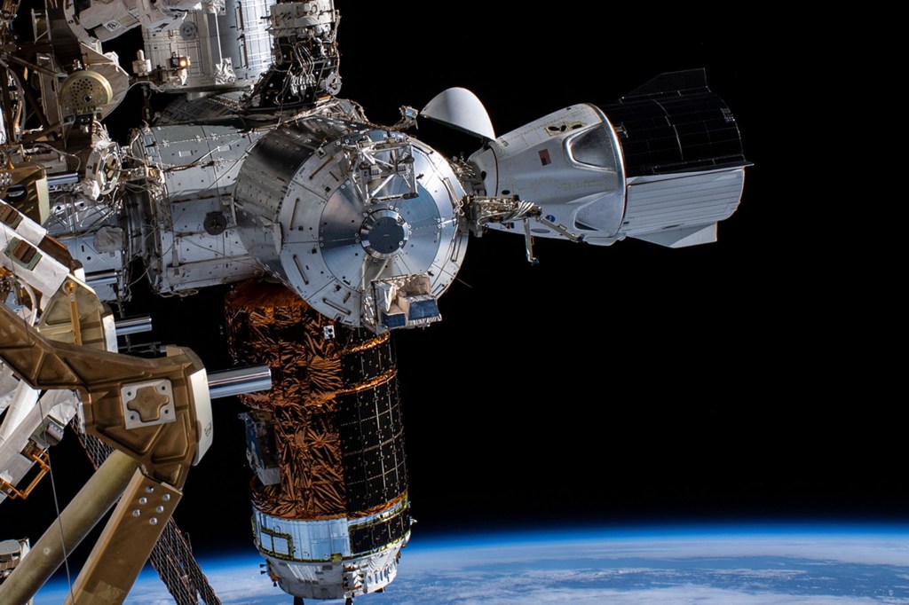
In Space Production Applications News
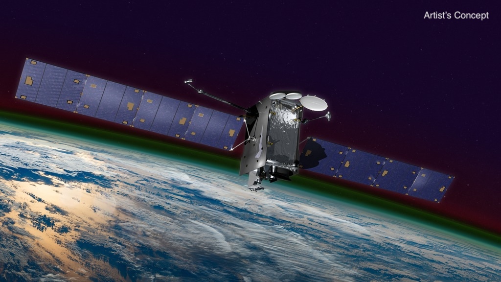
Alphabet Soup: NASA’s GOLD Finds Surprising C, X Shapes in Atmosphere

The 1998 Florida Firestorm and NASA’s Kennedy Space Center
NASA’s Planetary Radar Tracks Two Large Asteroid Close Approaches

What’s Up: July 2024 Skywatching Tips from NASA

Bente Eegholm: Ensuring Space Telescopes Have Stellar Vision
Hubble Examines an Active Galaxy Near the Lion’s Heart

NASA Science Activation Teams Present at National Rural STEM Summit
B.12 Heliophysics Data Environment Enhancements (HDEE) POC Change

A Wartime Necessity
NASA Prepares for Air Taxi Passenger Comfort Studies
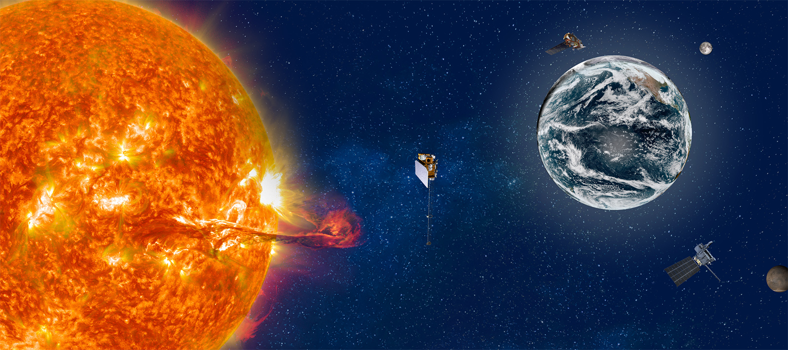
Slow Your Student’s ‘Summer Slide’ and Beat Boredom With NASA STEM
Mission Success: HERA Crew Successfully Completes 45-Day Simulated Journey to Mars
Astronauta de la NASA Frank Rubio
Diez maneras en que los estudiantes pueden prepararse para ser astronautas
Astronauta de la NASA Marcos Berríos
Spaceflight operations.
Introduction
Flight operations, medical and science operations, discipline specific operations.
The first word uttered by astronauts in space before history is made – big or small – is “Houston…” NASA’s Johnson Space Center (JSC) has served as the iconic setting to some of humankind’s greatest achievements, including the Apollo Moon landings and the Space Shuttle Program. JSC, a world leader in human spaceflight, has developed unique knowledge, skills, and capabilities over our decades-long experience operating human spacecraft.
JSC serves as a central hub for NASA’s human spaceflight operations, encompassing astronaut training, the Mission Control Center (MCC), International Space Station (ISS) operations, Commercial Crew and Cargo operations, operations considerations for spacecraft development, and ongoing support for new exploration space missions. Our MCC houses some of the world’s most experienced flight controllers and mission support personnel. These individual undergo rigorous training and have a deep understanding of spacecraft systems, procedures and emergency protocols. They provide real-time monitoring, analysis, and decision-making support for crewed space missions. While the MCC serves as the central nervous system for spacecraft operations, ensuring the safety and success of astronauts in space, it also serves as a hub for international collaboration, supporting missions not only for NASA, but also for other space agencies. We continually evolve our technology, procedures and infrastructure to adapt to changing mission requirements and advancements in space exploration, staying at the forefront of innovation in mission control operations. Overall, JSC’s MCC stands as a symbol of human ingenuity, collaboration, and dedication to exploring the cosmos and we invite our partners to join us on the journey. Explore our capabilities below to see where we can advance the boundaries of space exploration and innovation together.
Mission Control Center (MCC)
Overview | NASA Johnson Space Center is the worldwide leader in human spaceflight mission planning, training, test, and flight operations. The Mission Control Center (MCC) at JSC has unparalleled experience in supporting human spaceflight operations.
- 20+ years of accumulated on-orbit Mission Elapsed Time executing spaceflight operations
- More than 300 manned missions and 300+ Extravehicular Activities supported
- World class systems for mission design, test, training, command and control
- Full suite mission planning for ground, crew, and spacecraft communications and trajectory
- Terrestrial, low earth orbit, and deep space communications networks
- Robust and flexible intercom between flight controllers, vehicles, and remote locations
- Studio quality video backbone
- Designed for centralized or distributed operations support
- Reconfigurable command and control
- Key sub functions include Core Software, Application Software, and Recon Product Generation
- Scalable, redundant data and power systems
- Built on standardized interfaces
- Full life-cycle data storage and retrieval
- Fully integrated cyber and data security
- Fully capable off-site backup command and control system
- Support for simulation, vehicle test, flight follow, and playback
- Pre-flight, launch, landing, contingency, and recovery support
- Full mission life cycle weather support
- Ground systems and vehicle operations experts
- Proven ability to concurrently operate diverse, multi-class, multi-mission space vehicles
- Current Programs supported: International Space Station (ISS), Commercial Crew Program (CCP), SpaceX-Dragon, Orbital Cygnus, Boeing CST-100, Orion, and the Space Launch System
For further information, please see: https://www.nasa.gov/johnson/jsc-mission-control-center/
Mission Support Rooms/Operations Suites
Overview | The Mission Control Center (MCC) at JSC is designed to enable the configuration of multiple control rooms to support short or long duration dedicated activities. The MCC’s architecture is designed to support multiple simultaneous events with different partners and interfaces.
- Ground systems expert support to facilitate any unique development and integration tasks
- MCC consoles and control rooms can be reconfigured based on activity needs (simulation, test, real-time execution)
- MCC scheduling process enables the team to account for both hardware and network resources when scheduling events
- Available command and control includes communication, command, voice, video, timing, data record/archive, and other real-time capabilities
- Redundant data and power systems
- Pre-flight, launch, landing, contingency, and recovery support
Flight Control/Mission Execution
Overview | NASA JSC Flight Operations Directorate (FOD) flight controllers monitor and control all space flight phases for multiple crewed space vehicles. Mission execution is the culmination of all integrated support functions, flight planning and design, analysis and procedure development, and crew and flight controller training. Crew and flight controller teams work in tandem to execute all mission objectives safely and successfully.
Details | Flight systems control and management of: communications, computers/data, electrical, environmental control/life support, thermal, mechanical, propulsion, guidance and navigation, crew system, photo/TV, etc.
- Real-time operational support for all space flight phases: ascent, orbit/transit, docking, surface operations, entry and landing
- Nominal, contingency, and emergency operations execution
- Real-time planning and execution of daily operations
- Negotiate operational constraints with international partners, scientists and system experts to meet programmatic requirements
- Management and execution of vehicle trajectory plan and altitude strategy
- Proximity operations trajectory/rendezvous operations
- Real-time analysis of vehicle conjunctions and debris avoidance operations/maneuvers
- Real-time operations coordination with International Partner and other control centers
- Visiting vehicle (to orbital space station) operations integration
- Stowage and cargo transfer operations
- Vehicle system performance analysis, maintenance, and repair
- Vehicle commanding and uplink
- Extravehicular activity execution and real-time systems management
- Robotics operations
Worldwide Connectivity
Overview | Mission Control Center (MCC) provides worldwide connectivity as the central hub of communications for all human space flight operations.
- Worldwide network and communications connectivity support spacecraft operations
- Space Network Communications
- Low Earth Orbit (LEO)
- Near Earth Network (NEN)Deep Space Network (DSN)
- Tracking Infrastructure & Services
- Tracking and Data Relay Satellite System (TDRSS) & Scheduling
- Local Ground Station / Electronic System Test Laboratory (ESTL)
- Flight Dynamics Facility (FDF)S-Band Radiometric
- C-Band Trackers
- Interconnectivity to all NASA centers
- Connectivity with Vehicle Trainers, Flight Software (FSW), and Science Labs; International Space Station (ISS); Spacecraft System Test (SST), Integrated Test Rig (ITR), Software Development & Integration Laboratory (SDIL), Payload Operations Integration Center (POIC), Multi-Purpose Crew Vehicle/Space Life Sciences (MPCV/SLS), Integrated Test Lab (ITL), Engineering Data Library (EDL), operations and checkout (O&C), Space Systems Integration and Test Facility (SITF), System Integration Laboratory (SIL)
- Integration with Partner Control Centers: Canadian Space Agency (CSA), European Space Agency (ESA) – European Space Technology Center (ESTEC), Columbus Control Center (COL-CC), Italian Space Agency (ASI), Huntsville Ops Support Center (HOSC), Japanese Space Agency (JAXA), Orbital (Dulles), Russian Space Agency (TsUP), SpaceX (Hawthorne)
Operations Integration
Overview | NASA JSC Flight Operations Directorate (FOD) utilizes our operational expertise to support operational integration across programs and vehicles. Operational integration is necessary to ensure commonality and synergistic solutions among different elements. Cross program operations integration ensures that design decisions are made appropriately across multiple programs.
- Identify and assess cross-program and vehicle/element risks
- Ensure operational issues are integrated across all impacted stakeholders
- Concept of Operations and System Definition, Test and Certification Plans
- Development of notional timelines to help define and evaluate mission proposals
- Crew displays, interface development, integration and testing
- Spacecraft integration for proximity operations and docking
- Software and hardware limitations resolution and operational workaround design
- Telemetry/downlink definition and integration
- Payload command / telemetry and displays
- Master Verification Plan, Test & Verification Matrix, Verification Closure Notices
Real-time safety support
Overview | Safety and Mission Assurance offers safety operations support for real time, complex space station and vehicle operations.
- Provide training in setting up real time operations consoles
- Proved specific safety-related real time support, Safety Assessments, Chits, and Anomaly Reports
Space Medicine Operations
Overview | JSC provides specialized primary medical care for astronauts and expert medical and biomedical engineering support for all human spaceflight mission operations. JSC space medicine performs medical and behavioral selection and certification for flight, as well as surveillance care for former astronauts supported by the JSC spaceflight pharmacy and the wealth of data held by its spaceflight epidemiology group.
Clinical and Space Occupational Medicine
- Behavioral Health and Performance
- Medical and Behavioral astronaut Selection and Certification for Flight
- Hyper and Hypobaric Medicine
- Biomedical Engineering/biomedical Flight controllers
- Space Medicine Subject Matter Expertise
- Astronaut Strength, Conditioning, and Rehabilitation
- Missions Operations and Product Development for Medical Operations
- Space Radiation Analysis
- Spaceflight Epidemiology and Surveillance
- Spaceflight Pharmacy
- Eye Exam & Vision Testing
Science Operations
Overview | NASA JSC Astromaterials and Exploration Research Division (ARES) pioneered science operations for human missions through support to the Apollo missions, which has been leveraged to all subsequent crewed missions, including International Space Station (ISS) missions and Orion missions.
Details | The Astromaterials and Exploration Science Division (ARES) integrates science operations of Earth sensors onboard the International Space Station and leads the acquisition of Earth imagery by astronauts. We populate Mars mission teams, including the Curiosity, Opportunity, and Perseverance rovers. We also integrate into science teams for asteroid missions including Origin’s Spectral Interpretation Resource Identification Security Regolith Explorer (OSIRIS-REx) and Hayabusa2. We lead the development of sensors to enhance the scientific return of planetary exploration, leveraging the International Space Station as a proving ground as needed.
Tele Science Center
Overview | The Tele Science Center (TSC) provides a separate mission control room in the Houston Mission Control Center that allows for privatized video and communications to support NASA’s Human Research Program sponsored investigations.
Digital Voice Inter-Communications Equipment (DVICE) access
- Command path to Human Research Facility through Marshall Space Flight Center Payload Operations Center
- Live Station video
- Ability to Privatize Comm and video from ISS
- Realtime ISS telemetry
- Backup power from standby Generator
- MSE and MCE workstations
Decompression Sickness Mitigations
Overview | Johnson Space Center is a hub for decompression sickness research and management. Resident experts exist within research and operational aerospace medicine, dive medicine, dive physiology, decompression physiology, and exercise physiology, as well as a wide variety of engineering disciplines, including computer science and space suit engineering. This expertise coupled with cutting edge technology development enables NASA to implement leading prevention and treatment modalities for decompression sickness, not only in the operational high altitude and space environments, but in the diving environment as well.
Details | Johnson Space Center utilizes state of the art software systems to help experts better understand decompression physics and physiology by modeling tissue absorption of inert gases such as nitrogen, nitrogen bubble formation, and nitrogen offgassing during decompression. These analyses enable NASA to better assess the risk of decompression sickness during Center Operations and to help minimize and mitigate such risks. This includes the development of pre-breathe protocols to reduce risk of decompression sickness during extravehicular activities or during suit testing and the development of operational procedures to minimize decompression sickness risk during extravehicular activity training at the Neutral Buoyancy Laboratory (NBL).
- Pre-Diving Medical Risk Assessment and Mitigation
- Operational Medical Support
- Emergency Medical Response Procedures and Capabilities
Cold Stowage
Overview | The Cold Stowage team is part of the International Space Station (ISS) Program. JSC manages the operation, support and integration tasks provided by Jacobs Technology and the University of Alabama Birmingham (UAB). Cold stowage provides controlled environments to meet temperature requirements during ascent, on-orbit operations, and return, in relation to ISS payload science.
Details | NASA’s vision for humans pursuing deep space flight involves the collection of science in low earth orbit aboard the ISS. As a service to the science community, JSC has developed hardware and processes to preserve collected science on the ISS and transfer it safely back to the Principal Investigators. These active and passive cold stowage systems include an array of freezers, refrigerators, and incubators. JSC’s Cold Stowage Lab can perform hold tests, fit checks, and thermal tests by request. Equipment in the lab allows the team to test articles at temperatures ranging between -196° C to +200° C. The team also provides support to payload developers through launch, on-orbit operations, and landing.
Nutritional Biochemistry Laboratory
Overview | The primary goal of the Nutritional Biochemistry Laboratory is to keep crews healthy from a nutrition perspective on space missions. This includes determining the nutritional requirements for extended-duration spaceflight, and to develop, evaluate, and validate nutritional countermeasures to prevent or minimize the negative effects of long-duration spaceflight on the human. The activities cover both operations and research efforts. The primary operational activity is the support of the Clinical Nutritional Assessment profile, which includes biochemical assessments before and after International Space Station flights, along with dietary intake and body mass monitoring during these long-duration (4 to 6 month) missions. In addition to general dietary intake issues, several specific nutrients are also of concern, including vitamin D, folate, calcium, iron, and more.
Details | The role of nutrition in physiologic systems (e.g., bone, muscle, cardiovascular, ocular, and immune) during spaceflight is critical, as is the role in behavioral health and performance.
- Performing scientific expertise and support for nutrition-related research and studies of the role of genetics on nutritional requirements
- Collaborating and contributing to writing proposals and scientific articles
- Performing analysis of nutritional, biochemical and physiological markers (e.g., bone markers)
- Performing crew training on nutrition/diet
- Collecting/analyzing dietary intake data
- Providing dietary counseling
- Developing, evaluating and validating of nutritional countermeasures and technologies
- Collaborating with space food scientists to provide dietary and nutritional requirements for space food products tailored for each DRM
Radiation Monitoring, Protection and Exposure Analysis
Overview | The Space Radiation Analysis Group (SRAG) offers many unique capabilities at the intersection of technology development, data analysis, statistics, information technology, health care, and radiation safety. It deals with the resources, devices, and methods required to predict, monitor, and minimize crew radiation exposure.
Console Monitoring and Support
Johnson Space Center (JSC) has more than 50 years of operational spaceflight experience and provides round-the-clock solar radiation environment monitoring for human spaceflight operations support. SRAG also routinely participates in flight rule development; alert warning systems integration; and space weather forecast modeling. These four capabilities will help JSC ensure safe human spaceflight operations in the upcoming exploration missions beyond Low Earth Orbit.
Radiation Testing and Logistics
JSC routinely coordinates and conducts radiation instrument measurements at various medical and accelerator facilities around the world. These measurements are used for instrument calibration, algorithm development, requirements verification, and multi-instrument comparisons.
Radiation Monitoring and Measurements
JSC has unique expertise and capabilities to assess extreme environment operations, dosimetry, radiation environment measurements, and design and shielding analyses with a very strong reliance on information technology as well as leveraging technology development in radiation detection. JSC offers personal radiation exposure monitoring using personal active detectors. JSC also performs intra- and extra-vehicular radiation environment monitoring and characterization using many passive and active detectors (ranging from micro-dosimeters to charged/neutral particle spectrometers). Currently, JSC is utilizing the International Space Station (ISS) as a development/ certification testbed for future exploration-class instrumentation that will enable high fidelity measurements in simultaneous low mass/low power configurations.
Range Safety
Overview | Flight Operations Directorate (FOD) Flight Dynamics enables the execution of dynamic spacecraft operations for safe and successful human spaceflight missions.
- Range Safety analysis, flight rules, and tailoring of criteria for rocket launches and spacecraft reentry
- Assessment of public risk for re-entry or breakup of spacecraft
Navigation and Orbit Determination
- Orbit determination and spacecraft navigation updates for low earth orbit and cis-lunar space
- Utilization of C-band, TDRS, and Deep Space Network for spacecraft navigation
- Specialized tools for high-speed C-band tracking
Spacecraft Pointing and Attitude Determination
- Spacecraft attitude determination utilizing onboard sensors for star tracking and inertial measurement
- Spacecraft attitude analysis to meet thermal, power, or other spacecraft requirements
- Sensor pointing to meeting specific earth or lunar targeting requirements
Trajectory Design/Special Analysis
- Flight dynamics expertise provided across multiple programs and vehicles, always incorporating the crew perspective
- Development of launch windows, the ascent profile, ascent abort mode boundaries and representative abort trajectories
- Trajectories and impact predictions for launch vehicle stages and orbital insertion targets
- Deorbit opportunities, deorbit maneuvers, crew module to system module separation maneuvers and impact predictions
- Entry interface targets and entry corridors, and entry profiles for targeted landing sites
Rendezvous and Proximity Operations (RPO)
Overview | NASA JSC has expertise in Rendezvous & Proximity Operations (RPO) Guidance Navigation & Control (GN&C) and trajectory design, development, analysis and operations. RPO enables the execution of dynamic spacecraft operations for safe and successful human spaceflight missions.
NASA JSC performs systems requirement definition, analyses, design and testing necessary to support the development of rendezvous, proximity operations and docking (RPOD) Guidance Navigation & Control (GN&C) systems and to verify the compatibility of the designs with functional and performance requirements. We also provide operational considerations such as:
- Development of rendezvous techniques and manual piloting procedures
- Astronaut training for rendezvous and proximity operations
- Development of rendezvous techniques and manual piloting procedures
- Collision avoidance tools and techniques for spacecraft rendezvous and proximity operations
- Rendezvous maneuver plans and spacecraft separation maneuvers
Crew Exercise On-Orbit Systems Management
Overview | JSC is the world leader for providing sustaining engineering and systems management for exercise devices.
Exercise Flight Systems Operations
- Data collection and analysis
- Life tracking, sparing inventory and manifesting
- Preventive and corrective maintenance plans and procedures development
- Risk management
- In-flight anomaly investigation, troubleshooting and resolution
- Flight readiness assessments
Device Sustaining Engineering and Systems Management on ISS
- Treadmills (TVIS and T2/COLBERT)
- Bike (CEVIS)
- Resistive Exercise (IRED and ARED)
- Health Monitoring (BP/ECG and Heart Rate)
- Vibration Isolation and Stabilization (VIS)
Robotics Sustaining Engineering for Human-Rated Space Vehicles
Overview | Expertise is available in maintaining a safe efficient robotic capability to maximize science and robotic operational life and sustaining engineering and systems management for on-orbit robotics, including these on ISS, Gateway, and Low-Earth Orbit vehicle providers.
- Robotic Mission Planning Review (Procedure review/update, Flight Rules, etc.)
- Real-time robotics system expertise for nominal and off-nominal operations
- Anomaly investigation and resolution of technical issues with robotic systems and interfaces to dependent systems
- Define, update, and maintain robotic system requirements and verifications
- Review change proposals, waivers, deviations, and exceptions
- Perform trending of robotics systems health
- Integration support with external equipment
- Provide software build feature/capability priorities to robotic SW designers (in house or out)
- Testing and evaluation of payloads for robotic compatibility (including Flight Support Equipment and latching)
- Perform Berthing Camera/Target System implementation tasks for Visiting Vehicles and payload, including overlay development
- Visiting Vehicle robotic development support
- Integration of payloads as pertains to robotic compatibility
- Development of robotics requirements for payload handling
- Review exceptions to requirements and initial verification products
- Coordinate issues/concerns/questions with SMEs
- Review verification submittals
- Coordinate operations
- Robotics Human-Machine Interface
- Develop some integrated SW that utilizes vehicle telemetry to report data to users in intuitive ways
- Develop SW to assist operators in development of on-console products

Related Capabilities

Connect With Us
Whether you are a public agency, private company, or academic institution, we look forward to hearing from you.
- How it works
- Homework answers

Answer to Question #170993 in HTML/JavaScript Web Application for Chandra sena reddy
In this assignment, let's build a Book Search page by applying the concepts we learned till now.
Refer to the below image.
The page should perform the operation as shown in the following image link:-
https://assets.ccbp.in/frontend/content/dynamic-webapps/bookmark-maker-output.gif
Instructions:
- Add HTML input element with id searchInput inside an HTML container element
- Add HTML select element with id selectDisplayCount inside an HTML container element
- Add HTML container element with id searchResults
Use this Background image:
https://assets.ccbp.in/frontend/dynamic-webapps/book-search-bg.png
CSS Colors used:
Text colors Hex code values used:
CSS Font families used:
please help me.
Need a fast expert's response?
and get a quick answer at the best price
for any assignment or question with DETAILED EXPLANATIONS !
Leave a comment
Ask your question, related questions.
- 1. Manufacturing DateGiven a expiry date expiryDate and number of months before expiry monthsBeforeExpi
- 2. Product of values in the Sub-array(s)Given an array nestedArray of arrays, write a JS program to mul
- 3. Split and ReplaceGiven three strings inputString, separator and replaceString as inputs. Write a JS
- 4. String Starts or Ends with given StringGiven an arraystringsArray of strings, and startString, endSt
- 5. SubmarineGiven two numbers totalTorpedos, torpedosFired as inputs, write a super class Submarine wit
- 6. Arithmetic OperationsGiven a constructor function ArithmeticOperations in the prefilled code and two
- 7. MobileYou are given an incomplete Mobile class.A Mobile object created using the Mobile class should
- Programming
- Engineering

Who Can Help Me with My Assignment
There are three certainties in this world: Death, Taxes and Homework Assignments. No matter where you study, and no matter…

How to Finish Assignments When You Can’t
Crunch time is coming, deadlines need to be met, essays need to be submitted, and tests should be studied for.…

How to Effectively Study for a Math Test
Numbers and figures are an essential part of our world, necessary for almost everything we do every day. As important…

COMMENTS
Question #296146. Car Race. the goal of this code is to get output using with Classes. input. first line of input contains a string playerName. second line of input contains a number nitro. third line of input contains a number speed. output. the output contains multiple lines with the appropriate texts.
Method: GET. It should pass test conditions: When a value is provided in the HTML input element with id searchInput and Enter Key is pressed, an HTTP GET request should be made to the Books URL with the query parameter 'title' as the value of the searchInput element. When the HTTP GET request is successful, then the searchResults element should ...
Assignment #5: Launch Checklist Form¶ Using our knowledge of forms, the DOM, and HTTP, the commanders of our favorite space shuttle program asked us to create a quick launch checklist. We have four fields that need to be filled out with vital information: the pilot's name, the co-pilot's name, the fuel levels, and the mass of the cargo.
The spacewalk will last for three orbits around the earth. Use missionDuration to calculate how many hours the spacewalk will take. Use the candidate's o2Used method to calculate how much oxygen (O :sub:2) they consume during the spacewalk.Round the answer to 3 decimal places. Return the string, '__ will perform the spacewalk, which will last __ hours and require __ kg of oxygen.'
Be sure that math assignments completed by our experts will be error-free and done according to your instructions specified in the submitted order form. ... Programming. Answer to Question #302710 in HTML/JavaScript Web Application for chethan 2022-02-25T06:47:01-05:00. Answers > Programming & Computer Science > HTML/JavaScript Web Application.
Assignment 5: Launch Checklist. Using our knowledge of forms, the DOM, and HTTP, the commanders of our favorite space shuttle program asked us to create a quick launch checklist. We have four fields that need to be filled out with vital information: the pilot's name, the co-pilot's name, the fuel levels, and the mass of the cargo.
Here's the 5 step plan to a succesful dock: Orient: First, we want the spacecraft to point the right way (roll pitch and yaw). This makes navigating a lot easier. Translate: Then, we want to ...
SpaceX's historic CrewDragon has successfully launched into space on Saturday the 30th of May. The whole world had to hold their breath while watching the iconic moment of humanity coming into the new are of space flights. The Crew Dragon launched astronauts from the United States for the first time since the last Shuttle flight in 2011.
After showing the data on landing page the next task is to perform filter opertaion on the basis of Launch Year Button, Success Launch Button, Success Landing Button. I also perform filter operation on the landing page data by input filled of Launch Year , Success Launch & Success Landing.
The Launch Library 2 API is the official successor of the popular Launch Library API. It keeps its core features whilst also including everything the broader Space Launch Now API had to offer. The result is a large database delivering a more complete experience for each rocket launch and space event. The philosophy behind the API also remains ...
Expert system for space rockets launch decision-making on the basis of weather conditions - MinakovNV/Expert-system-for-space-rockets-launch-decision-making-on-the-basis-of-weather-conditions
Question #223927. isSubmerged It should contain a boolean value to indicate whether the submarine is submerged or not. dive When this method is called, it should set the value of isSubmerged to true and log "Submarine Submerged" text in the console. surface When this method is called, it should set the value of isSubmerged to false and log ...
Before they can launch to Mars, students need to learn more about where they're going and why. Moogega Cooper, a planetary protection engineer at NASA's Jet Propulsion Laboratory,
Yet Another Space Game (In 13kb of JavaScript) by Nicholas Carlini 2020-12-19. This year I entered in JS13K 2020, a game jam for JavaScript games in under 13KB (total size). I wrote a 3rd-person space shooter game, building on top of game engine I built last year for a doom clone . Clicking the video above (or HERE) will take you to the game.
[satellites] declares a new satellites property on the orbit-list component. ="displayList" sets the value of the satellites property to be the displayList array. Now, the orbit-list component has access to the fetched satellite data. To confirm this, change the orbit-list component html to use it's satellites property. When you can confirm that orbit-list has access to the satellite data ...
Use the correct assignment operator that will result in x being 15 (same as x = x + y ). Start the Exercise. Well organized and easy to understand Web building tutorials with lots of examples of how to use HTML, CSS, JavaScript, SQL, Python, PHP, Bootstrap, Java, XML and more.
Question #207550. Series of Operations. Given an array. myArray of numbers, write a JS program to perform the following steps and log the result. Multiply each value with 9. Subtract 20 from each value. Multiply each value with 7. Log the values of the resulting array separated by a space.
Space Invaders in JavaScript! Space Invaders. PLAY. CREDITS. Use A and D keys to move LEFT and RIGHT. Use W to SHOOT. Remember, you have a SHIELD wich protects you from damages, when it's over your SpaceShip will be damaged, wait 5s to restore your shield. LEVEL.
1. Problem Formulation. Spacecraft trajectory optimization is a complex and challenging area of research in astrodynamics. It involves determining an optimal trajectory for a spacecraft while considering specified initial and terminal conditions and minimizing or maximizing a chosen objective.
Part 1: Minimum Viable Quiz ¶. Create variables for: the candidate's name. a quiz question. the correct answer. the candidate's response. Use input() to ask for the candidate's name. Before moving to the next step, use print to verify that your code correctly stores the information. Display the question and prompt the candidate for an ...
Question #300124. Product Launch Section, Devices (Size < 900px):Devices (Size >= 900px): Instructions: For the devices less than 900px, the width of image should be 180px and for the rest of devices it should be 300px. The page should have the image on the right in devices equals to and above 900px. The page should have the image on the top in ...
20+ years of accumulated on-orbit Mission Elapsed Time executing spaceflight operations. More than 300 manned missions and 300+ Extravehicular Activities supported. World class systems for mission design, test, training, command and control. Full suite mission planning for ground, crew, and spacecraft communications and trajectory.
In this assignment, lets build a Book Search page by applying the concepts we learned till now. Refer to the below image. ... Be sure that math assignments completed by our experts will be error-free and done according to your instructions specified in the submitted order form. ... Programming. Answer to Question #170993 in HTML/JavaScript Web ...